2.1. Identify your board model
This guide will help you identify your Red Pitaya board model. Whether you are a first time user or an experienced developer, knowing your board model is essential for proper setup, configuration, and usage.
2.1.1. List of Red Pitaya board models
Red Pitaya offers several board models, each with its own specifications and features. The main board models are categorized into two generations:
Gen 2 boards (newer):
STEMlab 125-14 Gen 2
STEMlab 125-14 PRO Gen 2
STEMlab 125-14 PRO Z7020 Gen 2
STEMlab 125-14 TI
STEMlab 65-16 TI
Original Gen boards:
STEMlab 125-14
STEMlab 125-10
SDRlab 122-16
SIGNALlab 250-12
STEMlab 125-14 4-Input
2.1.2. How to identify your board model
Before starting to work with the Red Pitaya board, it’s helpful to know which Red Pitaya board you have. The easiest way to identify the board model is by looking at the physical characteristics and labels on the board itself.
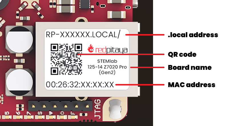
Check the sticker on the Ethernet connector: Most Red Pitaya boards have a sticker on the Ethernet port with the board model name and MAC address.
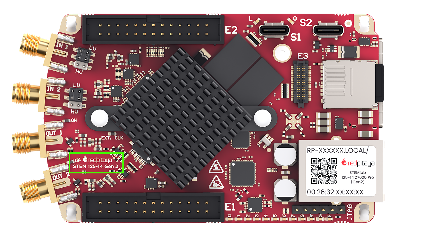
Look for the model name printed on the board: The model name is usually printed directly on the PCB near the center or edges of the board. Both top and bottom side of the PCB should be checked. While the printed model name may not always match the exact commercial name, it usually contains key identifiers such as “125-14”, “250-12”, or “65-16”, which correspond to different Red Pitaya models.
Visual comparison: If you’re still unsure, you can follow the visual comparison guide below to help identify your board model based on its layout and components.
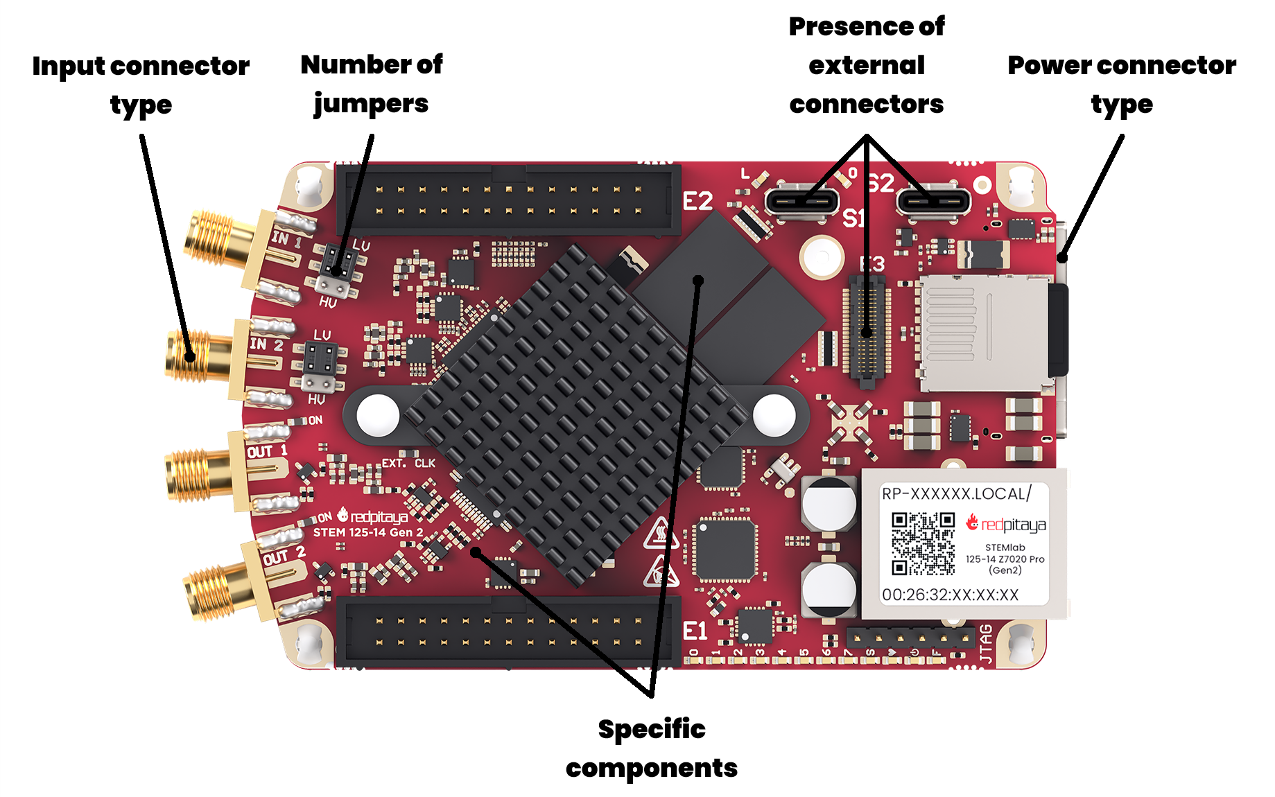
The key visual differences between the board models include:
Power connector type
Presence and type of external connectors (e.g., SMA, BNC)
Board size
Presence and number of jumpers
Specific component placements and configurations
2.1.3. Visual identification guide
Some board models are visually similar, so here is a detailed guide to help you distinguish between them. If you are still unsure about your board model after following this guide, please contact Red Pitaya support for assistance.
Gen 2 boards
The second generation of Red Pitaya boards features updated hardware and improved performance. They are easily distinguished by the USB-C power connectors. Here are the visual identifiers for each Gen 2 board model. The main reference model for comparison is the STEMlab 125-14 PRO Z7020 Gen 2.
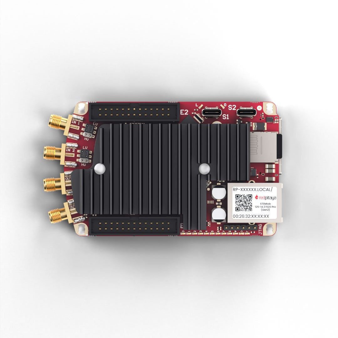
STEMlab 125-14 PRO Z7020 Gen 2
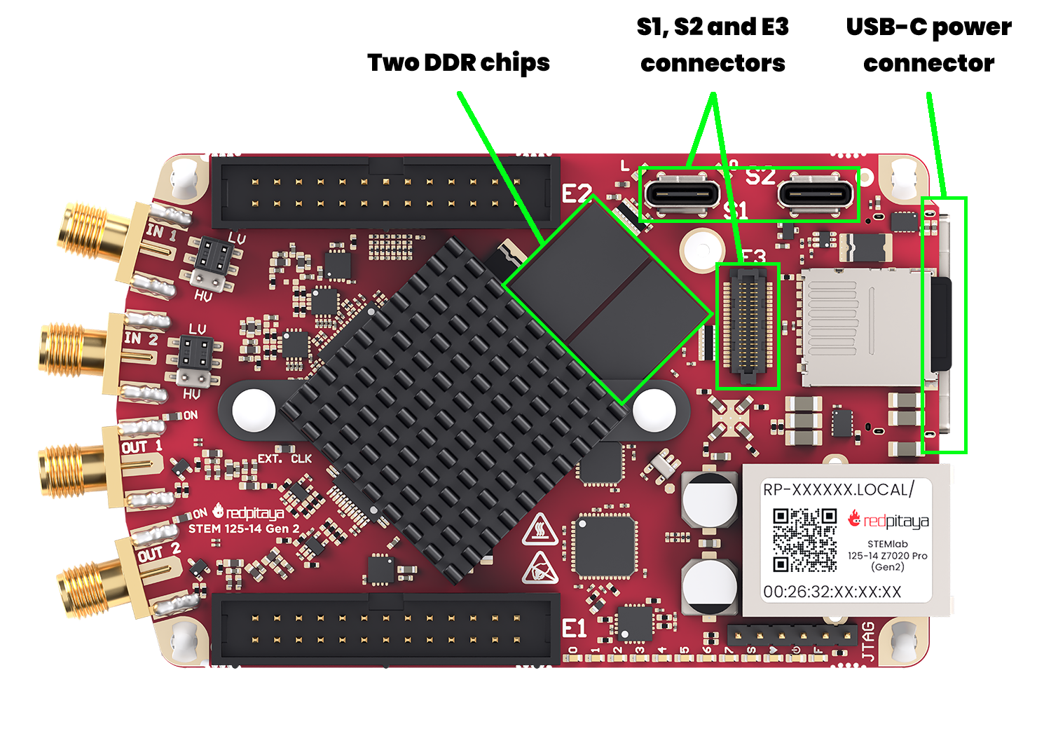
USB-C power and console connector
USB-C S1 and S2 connectors
E3 connector
Both DDR chips populated
For hardware documentation, see the STEMlab 125-14 PRO Z7020 Gen 2 hardware documentation.
STEMlab 125-14 PRO Gen 2
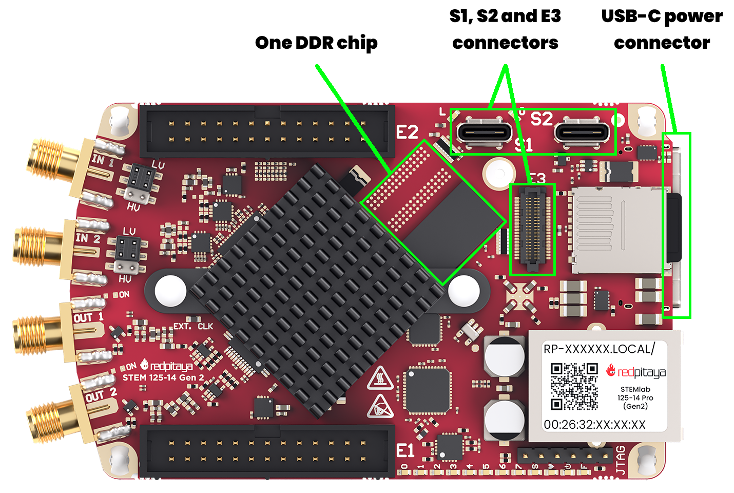
USB-C power and console connector
USB-C S1 and S2 connectors
E3 connector
Only one DDR chip present
For hardware documentation, see the STEMlab 125-14 PRO Gen 2 hardware documentation.
STEMlab 125-14 Gen 2
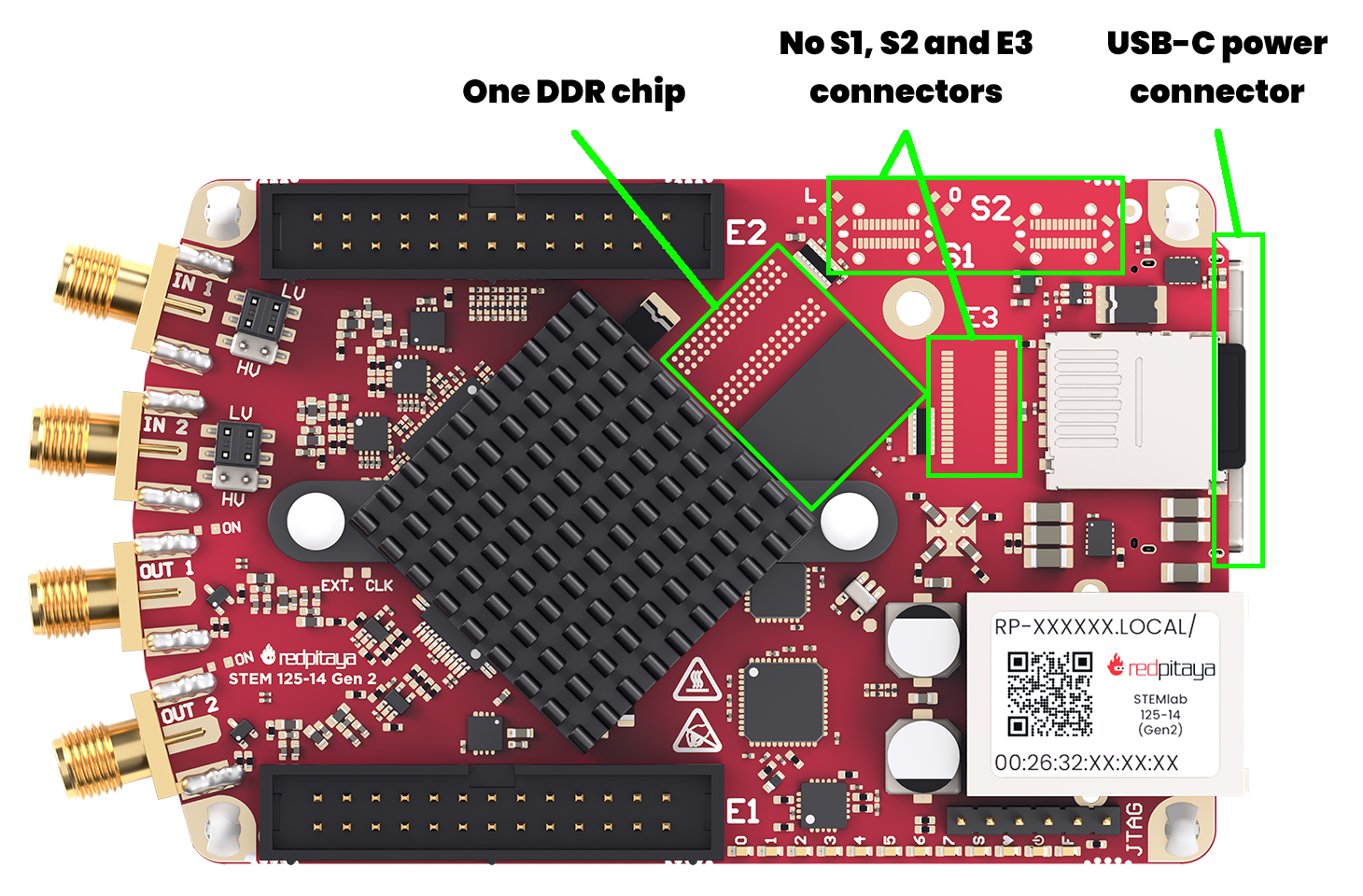
USB-C power and console connector
No USB-C S1 and S2 connectors
No E3 connector
Only one DDR chip present
For hardware documentation, see the STEMlab 125-14 Gen 2 hardware documentation.
STEMlab 125-14 TI

Huge heatsink covering most of the board
USB-C power and console connector
Almost indistinguishable from STEMlab 65-16 TI board - check the sticker on the Ethernet connector for confirmation
For hardware documentation, see the STEMlab 125-14 TI hardware documentation.
STEMlab 65-16 TI
Huge heatsink covering most of the board
USB-C power and console connector
Almost indistinguishable from STEMlab 125-14 TI board - check the sticker on the Ethernet connector for confirmation
For hardware documentation, see the STEMlab 65-16 TI hardware documentation.
Original Gen boards
The original generation of Red Pitaya boards includes several models with varying features. They can be identified by their power connectors and component layouts. The main reference model for comparison is the STEMlab 125-14.
STEMlab 125-14
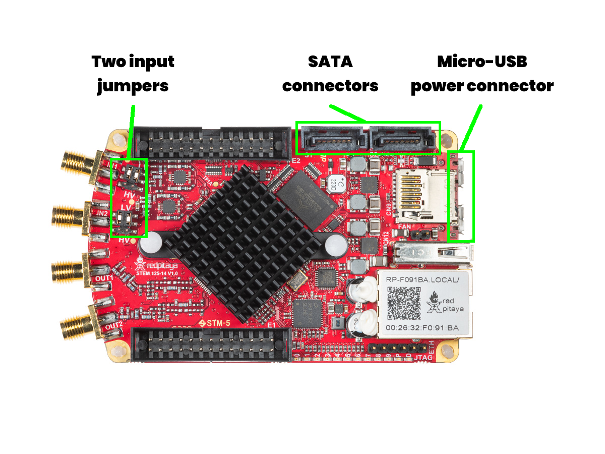
Micro USB power and console connectors
USB-A connector
SATA S1 and S2 connectors
Two input jumpers
For hardware documentation, see the STEMlab 125-14 hardware documentation.
STEMlab 125-14 also comes in five different variations, which are extremely hard to differentiate visually:
We recommend checking the sticker on the Ethernet connector for confirmation of the exact variation. Usually, the boards also include a sticker on the side of E1 connector. If you are still unsure, please contact Red Pitaya support for assistance.
STEMlab 125-10
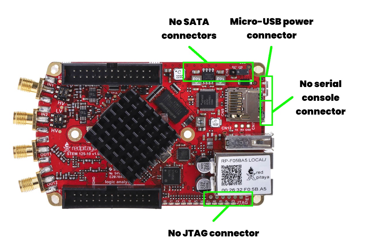
A single Micro USB power connector
USB-A connector
No SATA S1 and S2 connectors
Two input jumpers
For hardware documentation, see the STEMlab 125-10 hardware documentation.
SDRlab 122-16
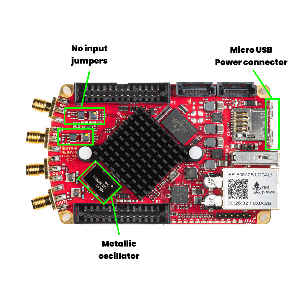
Micro USB power and console connectors
USB-A connector
SATA S1 and S2 connectors
No input jumpers
Metallic oscillator visible on the top side of the board
For hardware documentation, see the SDRlab 122-16 hardware documentation.
SDRlab 122-16 comes in two different variations, which are extremely hard to differentiate visually:
We recommend checking the sticker on the Ethernet connector for confirmation of the exact variation. If you are still unsure, please contact Red Pitaya support for assistance.
STEMlab 125-14 4-Input
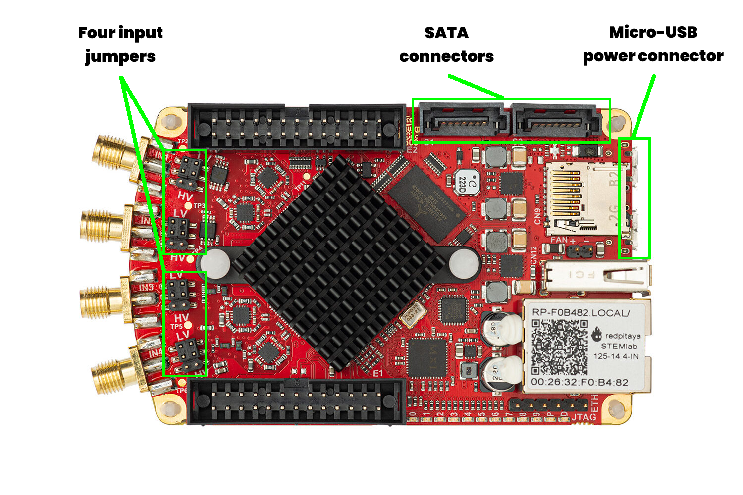
Micro USB power and console connectors
USB-A connector
SATA S1 and S2 connectors
Four input jumpers
For hardware documentation, see the STEMlab 125-14 4-Input hardware documentation.
SIGNALlab 250-12
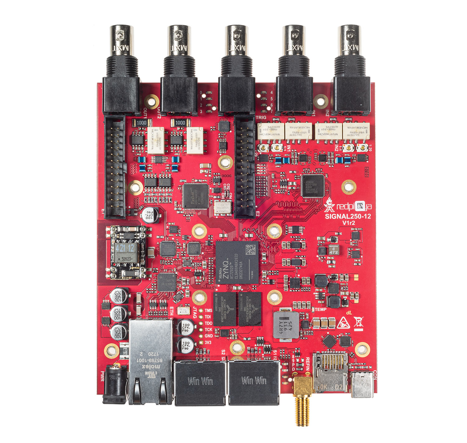
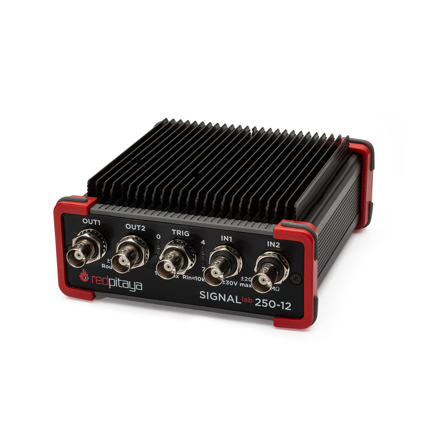
Bigger board size
BNC connectors for inputs/outputs
Enclosure
For hardware documentation, see the SIGNALlab 250-12 hardware documentation.