3.5.1. SCPI server (MATLAB, LabVIEW, or Python)
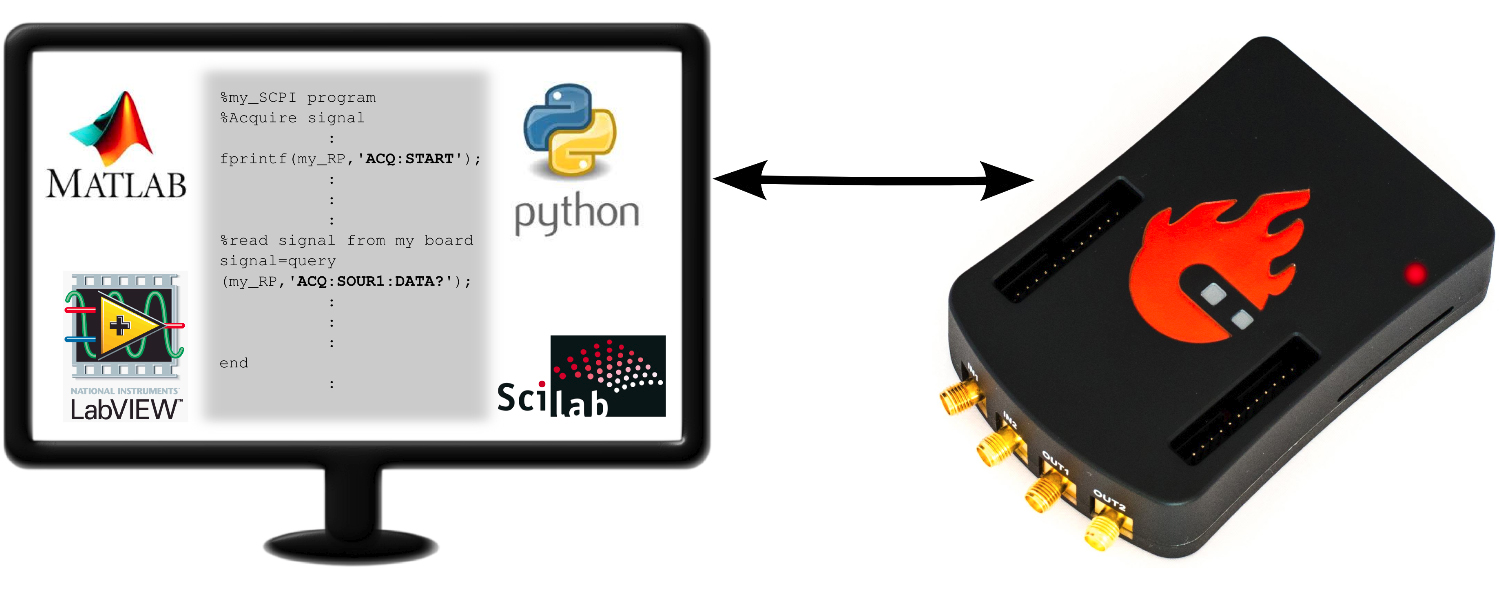
The Red Pitaya board can be controlled remotely over a LAN or wireless interface using MATLAB, LabVIEW, or Python via the Red Pitaya SCPI (Standard Commands for Programmable Instrumentation) list of commands. The SCPI interface/environment is commonly used to control T&M instruments for development, research, or test automation. SCPI uses a set of commands recognised by the instruments to enable specific actions (e.g., acquiring data from fast analog inputs, generating signals, and controlling other peripheries of the Red Pitaya platform). The SCPI commands are extremely useful when complex signal analysis is required. A software environment such as MATLAB that provides powerful data analysis tools is a perfect combination for the SCPI commands’ simple access to raw data acquired on the Red Pitaya board.
Features
Quickly write control routines and programs using MATLAB, LabVIEW, or Python.
Use powerful data analysis tools like MATLAB, LabVIEW, or Python to analyse raw signals acquired by the Red Pitaya board.
Write testing scripts and routines.
Incorporate your Red Pitaya and LabVIEW into testing and production lines.
Take quick measurements directly on your PC.
Note
Communicating with an SCPI server and working with web-based instruments at the same time can diminish the performance of your Red Pitaya. This is because the same resource is used for both tasks.
Quick start
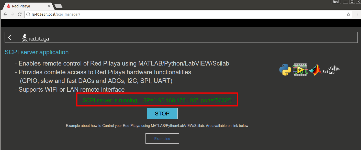
To initiate the SCPI server, just click on the SCPI server icon. Once the SCPI server is operational, your board’s IP address will be displayed. This IP address should be incorporated into your scripts. Alternatively, you can manually commence the SCPI server using the Terminal (refer to the instructions below).
To run an example, follow the instructions below:
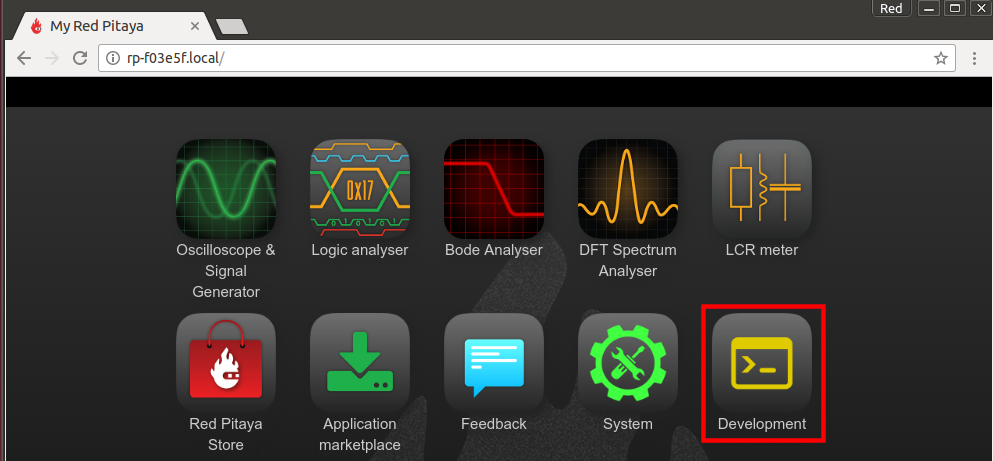
Open Red Pitaya web interface and navigate to the Development section.
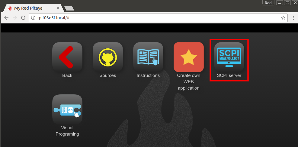
Open the SCPI server
Start the SCPI server by selecting one of the
RUNbuttons.TCP (Recommended) - Start the SCPI server with TCP protocol. It is the most commonly used protocol for SCPI communication and is compatible with most software environments that support SCPI commands.
UART - Start the SCPI server through the UART interface. This option is used for serial communication and is suitable for environments that support serial communication protocols.
Arduino - Start the SCPI server in Arduino mode. This option is designed for use with Arduino-based environments and allows for seamless integration with Arduino projects.
Arduino TCP - Start the SCPI server in Arduino TCP mode. This option combines the features of both TCP and Arduino modes, providing a versatile solution for various applications.

Note the IP address (in our case, 192.168.178.100) or the .local address (in our case, rp-f03e5f.local) of your Red Pitaya board, as it will be needed to establish a socket communication with your board.
Start programming. Follow the instructions below depending on the OS environment of your computer.
Stop the SCPI server by clicking the
STOPbutton when you are done.Note
Please refrain from running the SCPI server in parallel with other web applications like the Oscilloscope as it may result in undefined behaviour of both the application and the SCPI program.
To prevent undefined behaviour, the SCPI server application cannot be exited without clicking the
STOPbutton first on the latest OS versions.
MATLAB
Requirements and Setup
The basic MATLAB installation already has everything you need to control your Red Pitaya. However, we recommend installing the Signal Processing and Instrumentation Control toolboxes, which might come in handy.
Running code
Open MATLAB on your computer.
Copy blink example code. In the MATLAB workspace, paste the code from the blink tutorial example.
Replace the IP in the example with the IP of your Red Pitaya board or the “rp-xxxxxx.local” address.
Run the example. Hit
RUNor theF5key on your keyboard to run the code.
More examples of controlling Red Pitaya through MATLAB can be found here.
Python
Requirements and Setup
Python is a powerful programming language that is widely used for scientific computing, data analysis, and automation. It has a large ecosystem of libraries and tools that make it an excellent choice for controlling the Red Pitaya board remotely. It is also a great option for users who prefer an open-source solution or are looking for a more flexible programming environment.
Here we present setting up the environment in Visual Studio Code, due to high adaptability and easily expandable functionality. However, you can use any other coding environment that supports Python.
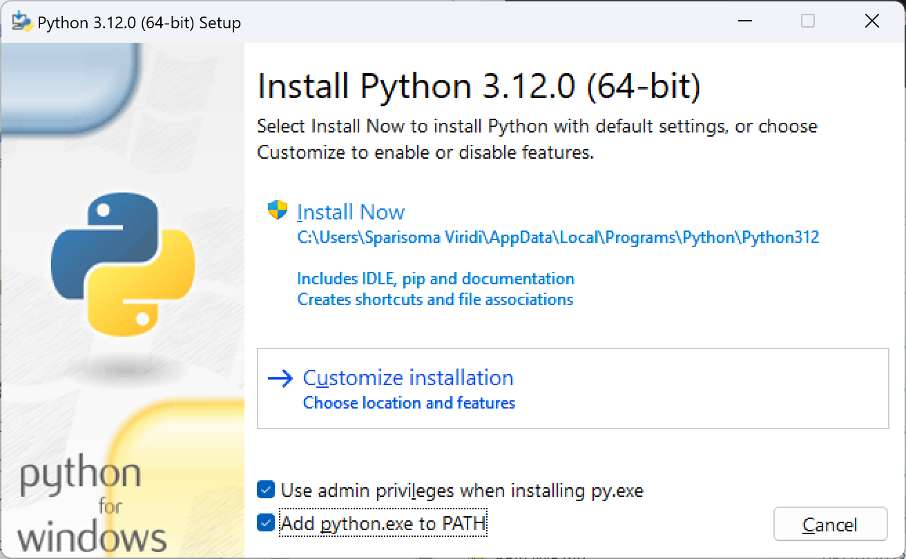
Install Python version 3.10 or higher. Link to Python download webpage.
Add python.exe to PATH during the installation process (check the box)!
Install a coding environment. We recommend using Visual Studio Code.
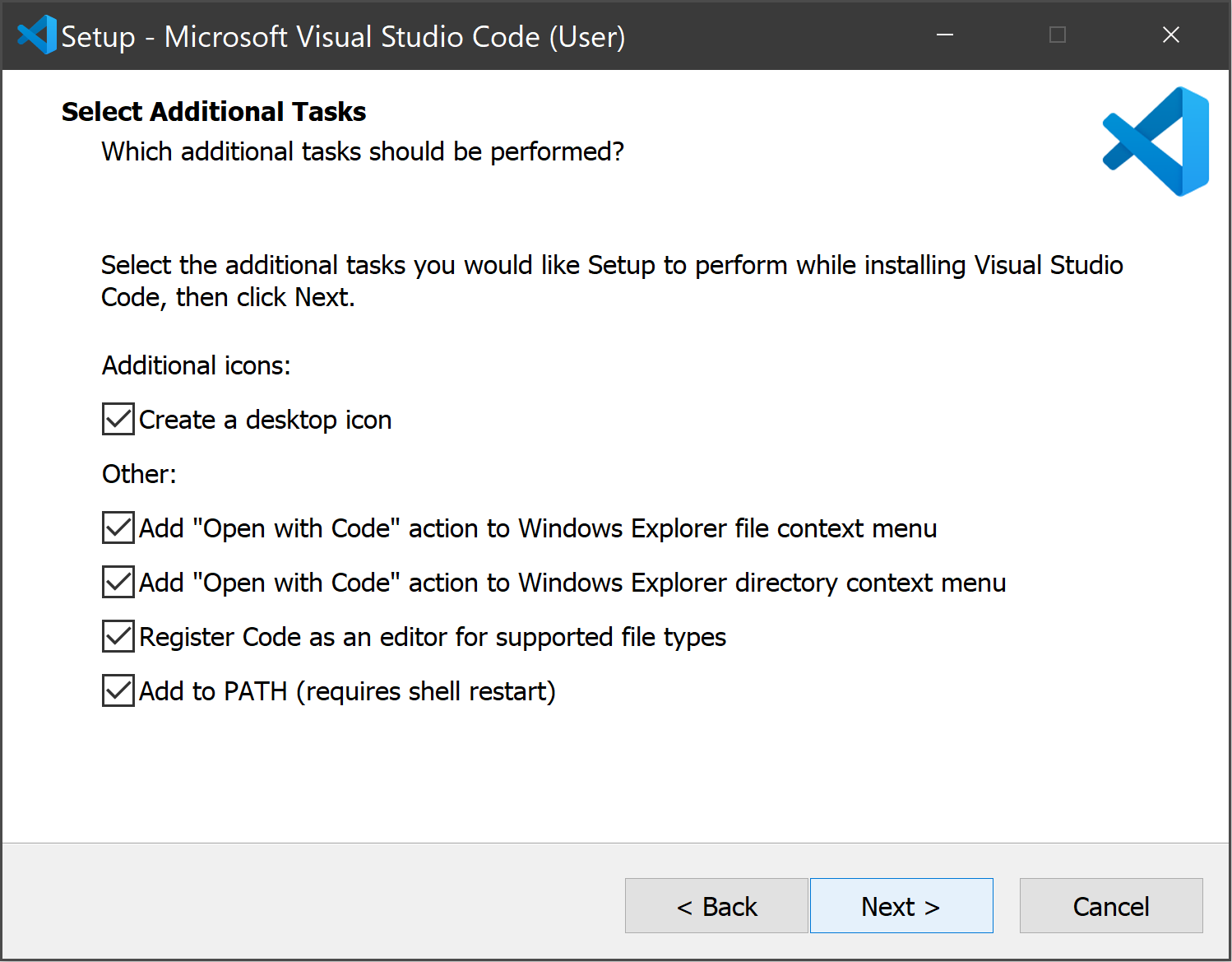
Install extensions for your coding environment (Python Extension Pack and Better Comments are a good combination for VS Code).
Configure the workspace. Setup or create a new workspace. Here are some tutorials for Visual Studio Code.
Create a virtual environment (optional). See the instructions here - virtual environment.
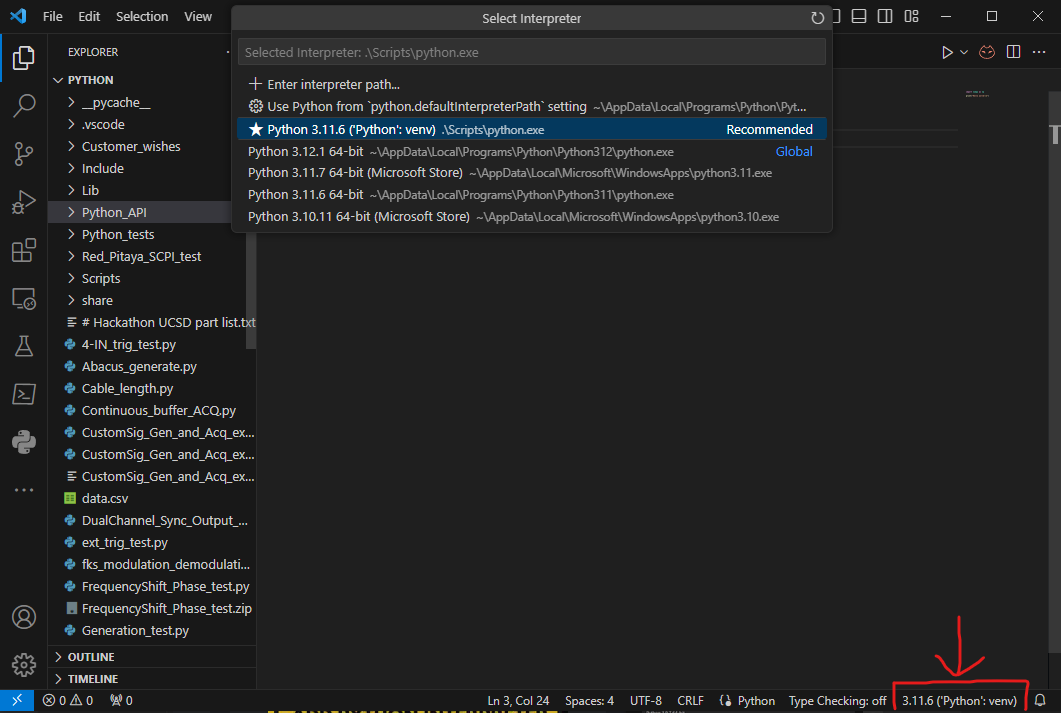
Choose a Python interpreter.
Update Python packages. Ensure that the Python packages are up to date and install following Python libraries:
numpy
matplotlib
Open the Terminal or use the Terminal in VS Code and type:
sudo pip3 install numpy matplotlibOpen the Command Prompt or use the Terminal in VS Code and type:
py -m pip install numpy matplotlibEnable “Running Scripts” option. Windows users must enable
Running Scriptsoption. It should be located in Settings > Update&Security > For developers under the Power Shell section (or googleHow to enable running scripts on Windows 10/11).Double-check the Python version and reselect the Python interpreter if necessary (See step 5).
$ python --version
Python 3.11.6
On Windows, you can use py instead of python in the command line.
Download and save the redpitaya_scpi.py library into the VS Code workspace folder/directory. This library must be in the same folder as the python scripts. You can find the source code of the library on GitHub: redpitaya_scpi GitHub source code. Alternatively, you can download it directly from here:
redpitaya_scpi.py.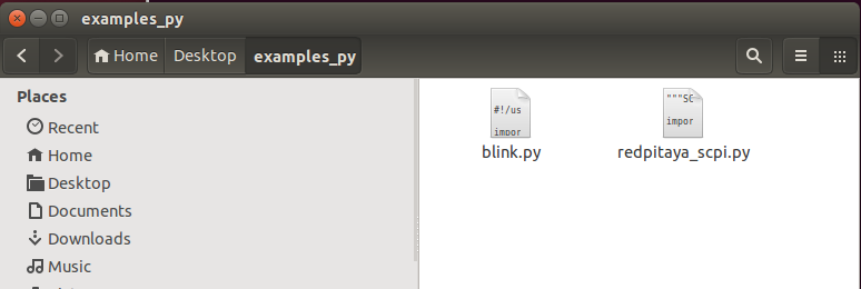
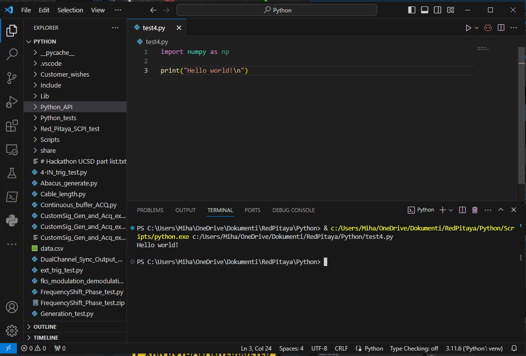
Create a new python file with the following code. Once saved, check how the NumPy library is displayed. If it is underlined in yellow the current Python environment does not have the libraries installed correctly.
import numpy as np

print("Hello world!\n")
Run the test file. There should be no errors or warnings displayed in the terminal (“Hello world!” is printed).
redpitaya_scpi.py library
The redpitaya_scpi.py library is a Python script that establishes a socket connection between your computer and the Red Pitaya board. It provides an easy-to-use interface for sending SCPI
commands to the Red Pitaya board and receiving responses. The library is designed to be simple and intuitive, allowing you to focus on writing your control routines without worrying about the
underlying communication details.
The library provides access to the following functions:
Function |
Description |
|---|---|
__init__(ip) |
Initializes the connection to the Red Pitaya board using the provided IP address. |
__del__() |
Closes the socket connection when the object is deleted. |
check_error() |
Checks for errors in the response. |
close() |
Closes the socket connection to the Red Pitaya board. |
rx_txt() |
Receives a text response from the Red Pitaya board. |
rx_txt_check_error() |
Receives a text response and checks for errors. |
rx_arb() |
Receives binary data from the Red Pitaya board. |
rx_arb_check_error() |
Receives binary data and checks for errors. |
tx_txt(txt) |
Sends a text command to the Red Pitaya board. |
tx_txt_check_error(txt) |
Sends a text command and checks for errors in the response. |
txrx_txt(txt) |
Sends a text command and receives a text response. |
The tx functions are used to send commands to the Red Pitaya board, while the rx functions are used to receive responses. The check_error functions are used to check for
errors in the responses. The library also provides a simple interface for sending and receiving binary data.
Note
If an incorrect command is passed to the Red Pitaya board or an error occurs during the execution of a command, the rx functions will not return any data, resulting in an infinite loop as the program waits for a response that will never arrive. To avoid this, please ensure that the SCPI commands are grammatically correct and regularly check for errors using the check_error function after sending a command.
The GitHub repository of the redpitaya_scpi.py library contains several different libraries:
redpitaya_scpi.py - the main library for controlling the Red Pitaya board which also includes the optional functions for easier control of the Red Pitaya board (core functionality is included).
redpitaya_scpi_core.py - the core library that contains only the essential functions for establishing a connection and sending/receiving data.
old - contains older versions of the library that are no longer maintained.
You can find the source code of the library on GitHub here:
Running the code
Copy blink example code. Open the blink tutorial and copy the code to your favourite text editor.
Save the blink example to your “work” folder as
blink.py. Make sure that redpitaya_scpi.py is located next to it.Note
The
redpitaya_scpi.pylibrary is a standard script needed to establish the connection between your PC and the Red Pitaya board. The execution of your code will fail without this library being in the same folder as your Python code.
Change the IP address. Modify the
IPvariable in theblink.pyso that it contains the IP or the “rp-xxxxxx.local” address of your Red Pitaya.Run the example. Either select the left arrow in the upper right corner of VS Code or open the
Terminaland navigate to the folder containing your Python script (examples_py), then type:python blink.pycd <python_file_location> python blink.py
More examples of how to control Red Pitaya with Python can be found here.
Note
Python examples can also be run directly from the RP device itself. To do so, first start the SCPI server and then use the local device IP: 127.0.0.1
LabVIEW
Requirements and Setup
For proper operation, the Red Pitaya LabVIEW driver must be installed. The driver is functional; additional examples and code updates will be added in the future.
Download the Red Pitaya LabVIEW driver from Framatome GitLab.
Unpack the downloaded archive and copy the RedPitaya driver folder into the
instr.libfolder of your LabVIEW installation. The required path for LabVIEW 2020 32-bit (e.g. the free Community Edition) is:C:\Program Files (x86)\National Instruments\LabVIEW 2020\instr.lib
For other LabVIEW versions adjust the year and the
Program Files/Program Files (x86)folder accordingly (64-bit builds install underProgram Files).Note
If you are using a newer version of LabVIEW, the driver can be upgraded from within LabVIEW itself by saving the library in the newer format. This does not affect the functionality of the driver.
Restart LabVIEW after copying the folder.
The Red Pitaya cores are then available in the Block Diagram under:
Block Diagram → Functions → Instrument I/O → Instr Drivers → RedPitaya
Note
Depending on your settings, the Instrument I/O palette may be hidden. Please consult LabVIEW Help on how to show or hide palette categories.
Running code
You can access example VIs by going to:
Help -> Find Examples…
select the Search tab
In the Enter keyword(s) field, type RedPitaya.
More examples on how to control Red Pitaya from LabVIEW can be found here.
Starting SCPI server manually
Establish SSH connection. Connect to your Red Pitaya through SSH.
Stop the Nginx service. Before starting SCPI server, make sure Nginx service is not running. Running them at the same time will cause conflicts, since they access the same hardware.
systemctl stop redpitaya_nginxNote
This only stops the web interface temporarily. It will restart on next boot. For service management details, see Service Management.
Start the SCPI server with the following command:
systemctl start redpitaya_scpi &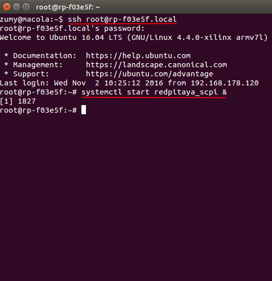
Note
Please make sure that the “default” v0.94 FPGA image is loaded. With OS versions 2.00-23 or higher, execute the following command:
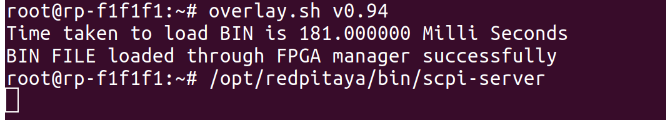
To see the server logs when executing commands:
RP:LOGmode CONSOLE
Starting SCPI server at boot time
The next commands will enable running SCPI server at boot time and disable Nginx service.
systemctl disable redpitaya_nginx
systemctl enable  redpitaya_scpi
Note
These commands configure which service starts at boot. For more service management options, see Service Management.
How do SCPI commands work?
Here we explain the “behind the scenes” functionality of the redpitaya_SCPI.py script, which establishes the socket connection between Red Pitaya (host) and the computer (client). The principles explained here can also be applied to other environments that already support SCPI commands (MATLAB, LabVIEW), or used as a basis for developing a script that enables SCPI commands in another environment.
SCPI commands are basically string commands that either contain a user-defined parameter that needs to be changed in the board settings, or are a request to the board to return a specific setting or captured data. Consequently, we can divide the SCPI commands into two categories, control commands and query commands, which we will discuss in the following chapters.
SCPI commands are easy to use and memorise, but suffer from a lack of speed because all data, regardless of size or type, must be converted into a string which is then sent over the TCP connection. When an SCPI command string arrives at the Red Pitaya board, it is compared with the list of all possible SCPI commands, if the correct command is found, the parameters are taken from the string and converted back into the usual format, then the appropriate C++ API function is executed. Otherwise an error is returned.
Control commands
Control commands send user-defined settings to the Red Pitaya.

Control commands never return anything.
Error checking is done via the status byte.
Error checking is optional.
The error code from the API consists of two parts.
9000or9500, indicating whether the error is normal or critical, and the API error number. For example:9500 + RP_EOED = 9501(Failed to Open EEPROM Device)
Query commands
Query commands request data or a setting to be returned to the user. They always have a question mark (?) at the end.

Query commands always return data.
Error checking via status byte.
Error checking is optional.
The data returned by the command can be of two types: binary data and text data.
Binary data response has the format
#<DATA SIZE><BYTES>. If an error occurs, the response format is as follows#0.Text data format:
<ANSWER>\r\nor<ANSWER>;<ANSWER>;...;<ANSWER>\r\n(If you’re sending multiple commands at once.) If an error occurs, the response format will be like this:\r\n.In ASCII mode, data buffers are represented in the form
{dd,dd,dd,...,dd}.The API error code consists of two parts.
9000or9500, indicating whether the error is normal or critical, and the API error number. For example:9500 + RP_EOED = 9501(Failed to Open EEPROM Device).