3.2.1. Oscilloscope & Signal Generator
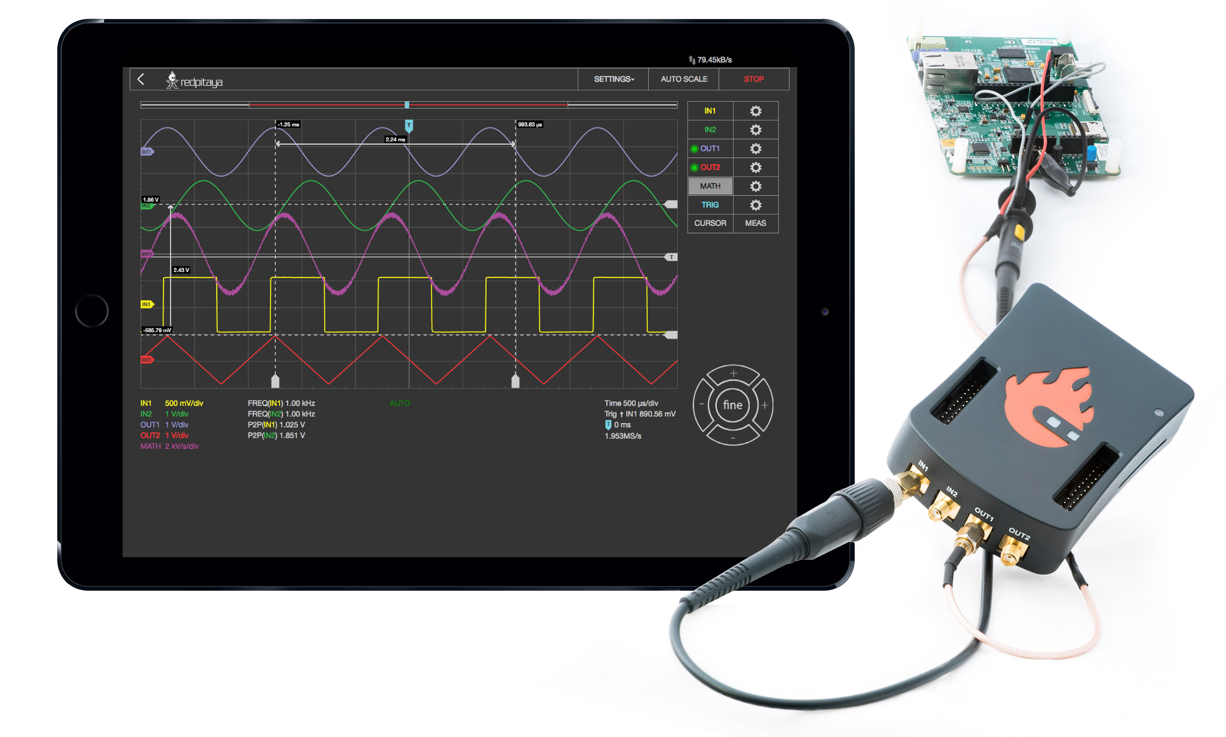
This application will turn your Red Pitaya board into a 2-channel oscilloscope and a 2-channel signal generator. It is the perfect tool for educators, students, makers, hobbyists, and professionals seeking affordable, highly functional test and measurement equipment. The simple and intuitive user interface provides all the necessary tools for signal analysis and measurements.
High-end specifications will satisfy more demanding users looking for powerful tools for their workbenches. The application is web-based and doesn’t require the installation of any native software. Users can access them via any web browser (Google Chrome is recommended) using their smartphone, tablet or a PC running any popular operating system (MAC, Linux, Windows, Android, and iOS). The elements in the Oscilloscope & Sig. Generator applications are arranged logically and offer a familiar user interface.
Note
STEMlab 125-14 4-Input has an oscilloscope, and it does not have a signal generator.
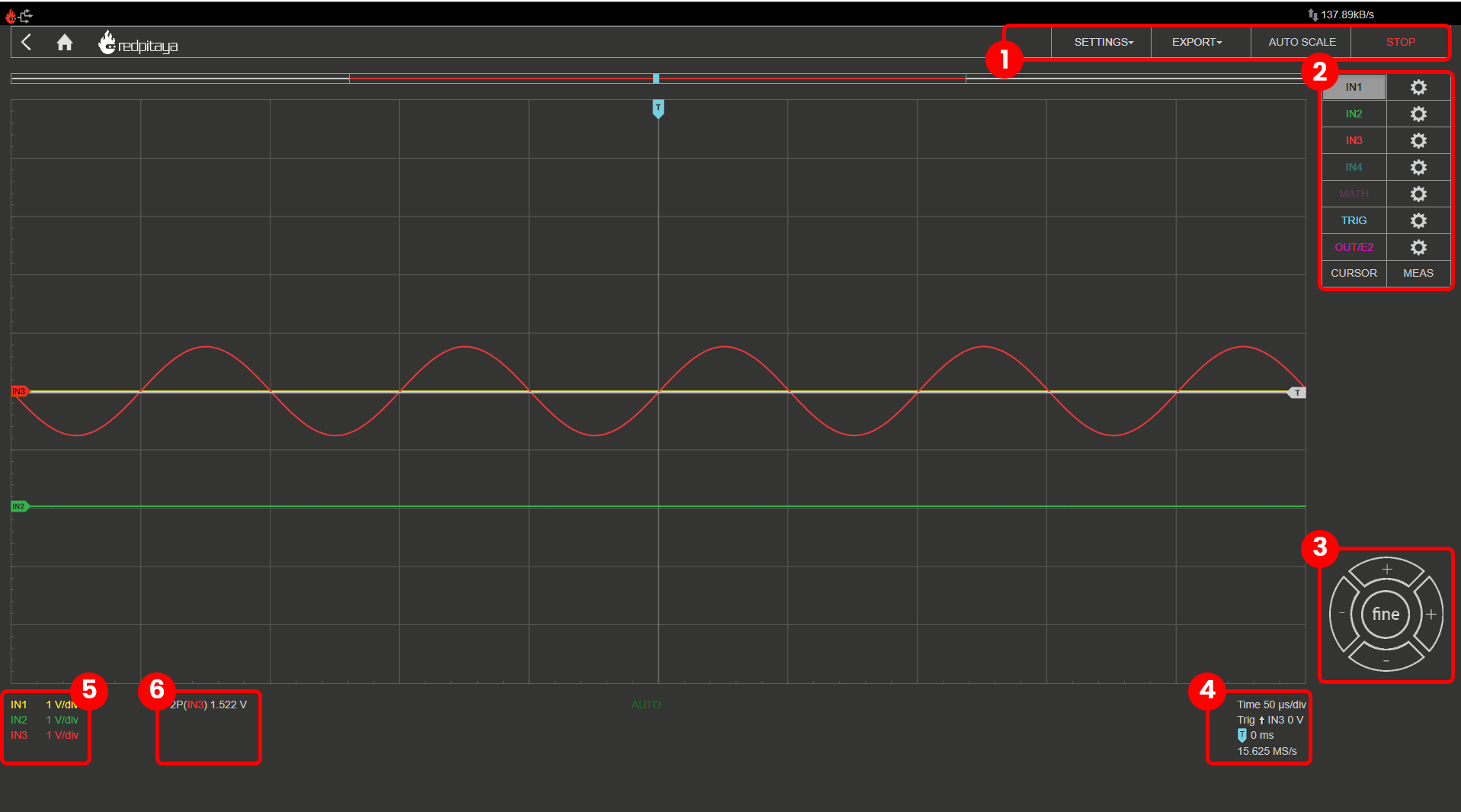
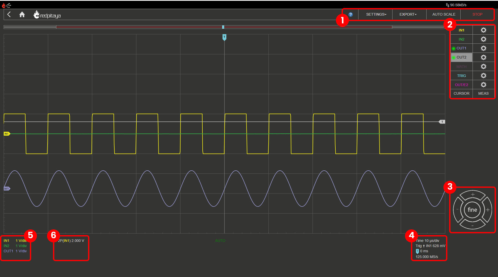
Apart from the graph, there are six areas in which the surface is divided:
Top Settings Menu: Includes basic functionality like Settings, Exporting data, Autoscale and Running/Stopping the measurements.
Channels / Trigger / Measuring Tools: This menu provides control over inputs and outputs, triggers, guides, and measurements.
Axis Control Panel: By pressing the horizontal ± buttons, the time axis (X axis) scale is changed. The vertical ± buttons change the amplitude axis (Y axis) and thus the displayed voltage range of the signal.
Time and Trigger Info: Displays the current time scale per division, trigger settings (time frame, trigger, zero point of the X-axis) and sampling rate.
Channel Amplitude Scale: Indicates the Y axis scale for all displayed channels.
Measurements Display: Displays the results of performed measurements.
Features
The Oscilloscope & Signal generator’s main features are listed below:
Run/stop and auto-set functionality
Signal position and scale control
Trigger control (source, level, slope)
Trigger modes: auto, normal, and single triggering
Cursors
Measurements
Mathematical operations
Signal generator control (waveform, amplitude, frequency, phase)
Custom waveform output (Arbitrary waveform generator)
Control over slow analog inputs and outputs
Top Settings Menu
Provides control over the Oscilloscope application. The blue question mark leads to this exact documentation page.
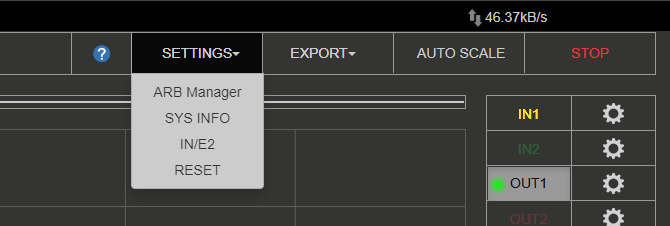
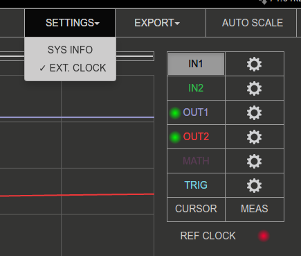
Settings
Includes the following settings:
ARB Manager - Goes directly to the Arbitrary Waveform Manager application, where a custom waveform can be uploaded for generation.
Sys Info - When checked, the Oscilloscope Application displays System information like, FPS, CPU Load, etc. in the bottom left corner of the application.
IN/E2 - When checked, displays the voltages from slow analog inputs of the E2 connector.
Reset - Resets all Oscilloscope and Signal Generator settings to default versions.
Ext. Clock (only SIGNALlab 250-12) - Enables the External Clock synchronisation for the SIGNALlab. For more info see the chapter below.
Stop/Run - Stops/Starts the data acquisition/Oscilloscope. When STOP, the application ignores any trigger conditions.
External reference clock (only SIGNALlab 250-12)
The external reference clock input can be enabled through the settings menu. Once enabled, its status is displayed in the main interface. The “green” status indicates that the sampling clock is locked to the external reference clock.
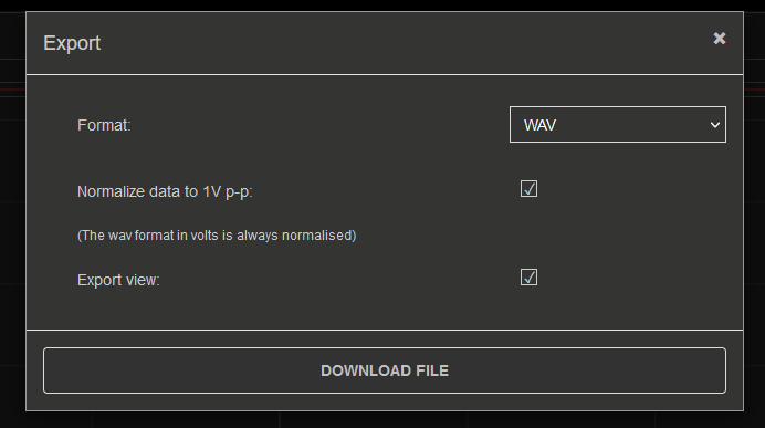
Export
Exports the currently displayed data as either a “Graph” or a “File”. If graph is chosen, a screenshot of the application is taken and automatically downloads via the browser. Otherwise, the data is exported in either WAV, CSV, or TDMS format, with the ability to normalize the data and export the view.
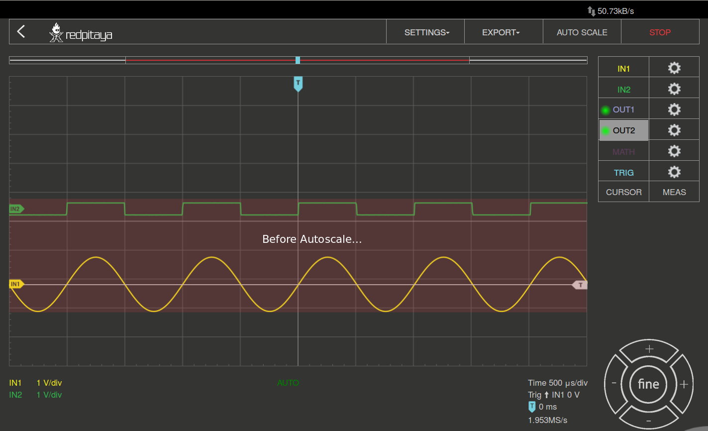
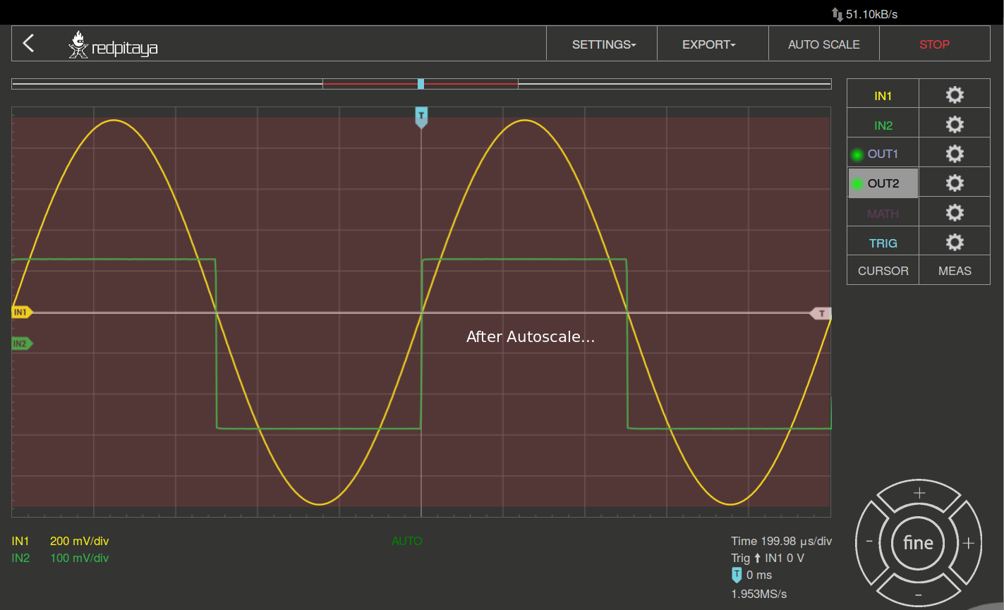
Autoscale
Automatically sets up the Oscilloscope to best display the input signal. By pressing this button, the voltage axis and the time axis are set so that at least one full period of the signal fills the screen.
Inputs
On the right side of the Oscilloscope & Sig. Generator application interface, the IN1 and IN2 channels are listed. With a simple click on the name of a channel (not the gear), the channel gets highlighted, and you can simply control all the settings of the respective channel. The available settings by device model:
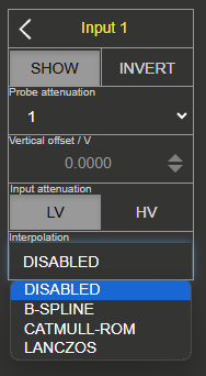
SHOW: Shows or hides the curve associated with the channel.
INVERT: Reflects the graph on the X-axis.
Probe attenuation: (must be selected manually) The division that was set on the probe.
Vertical offset: Moves the input curve up or down.
LV and HV: Must be selected according to the jumper position on each channel.
Interpolation: See Interpolation below.
Trace Mode: See Trace Mode below.
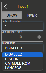
SHOW: Shows or hides the curve associated with the channel.
INVERT: Reflects the graph on the X-axis.
Probe attenuation: (must be selected manually) The division that was set on the probe.
Vertical offset: Moves the input curve up or down.
Interpolation: See Interpolation below.
Trace Mode: See Trace Mode below.
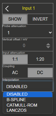
SHOW: Shows or hides the curve associated with the channel.
INVERT: Reflects the graph on the X-axis.
Probe attenuation: (must be selected manually) The division that was set on the probe.
Vertical offset: Moves the curve up or down.
Input attenuation: 1:1 (± 1V) / 1:20 (± 20V) is selected automatically when adjusting the V/div setting; the user can also select the range manually through the web interface.
AC/DC coupling: Select input coupling.
Interpolation: See Interpolation below.
Trace Mode: See Trace Mode below.
Interpolation
Controls how the sampled data points are rendered between each other on screen. When disabled (default), individual samples are shown directly as discrete points. When enabled, samples are connected using one of the following algorithms:
Linear — straight lines between samples.
B-Spline — smooth curve fitting.
Catmull-Rom — smooth curve that passes exactly through each sample point.
Lanczos — high-quality reconstruction filter.
Trace Mode
When Trace Mode is enabled, historical waveform data is retained on the screen as new data arrives, creating a persistence display similar to analog oscilloscopes. This allows visualisation of signal variations and rare events over time.
The following options are available:
Fast mode: Optimises the trace rendering for high data throughput.
Inverted opacity: Reverses the opacity of the trace, so older data appears brighter and newer data appears dimmer.
Trace colour selection: Select the colour scheme used to represent the density of data points — frequently occurring values appear in one colour while rare values appear in another.
Outputs
Note
Please note that the output waveform displayed in the user interface is for reference only and does not accurately represent the phase of the output signal. The output waveform is aligned to the beginning of the screen, while the input waveforms are aligned to the time offset cursor.
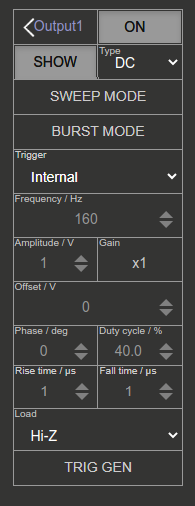
On the right side of the Oscilloscope & Sig. Generator application interface, the OUT1 and OUT2 channels are listed. With a simple click on the name of a channel (not the gear), the channel gets highlighted, and you can simply control all the settings of the respective channel. The available settings are the following:
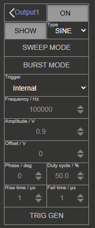
ON: Turns the generator output ON/OFF.
SHOW: Shows a signal preview (notice that the signal is not phase aligned with the input/output signal).
Type: Various waveforms are available for output: SINE (sinus), SQUARE (rectangle), TRIANGLE (triangle), SAWU (rising sawtooth), SAWD (falling sawtooth), DC, DC_NEG, and PWM (Pulse Width Modulation). Custom waveforms supplied through the ARB Manager application also appear here.
SWEEP MODE: Configure the Sweep mode settings (See below).
BURST MODE: Configure the Burst mode settings (See below).
Trigger: Enables the user to select an internal or external trigger for the generator.
Frequency: Frequency of the output signal.
Amplitude: One-way amplitude of the output signal (referenced to GND).
Offset: DC offset.
Phase: Phase of the output signal.
Duty cycle: PWM signal duty cycle.
Rise/Fall time: Minimal rise and fall time for the output signal.
TRIG GEN: Manually trigger the signal generator.
ON: Turns the generator output ON/OFF.
SHOW: Shows a signal preview (notice that the signal is not phase aligned with the input/output signal).
Type: Various waveforms are available for output: SINE (sinus), SQUARE (rectangle), TRIANGLE (triangle), SAWU (rising sawtooth), SAWD (falling sawtooth), DC, DC_NEG, and PWM (Pulse Width Modulation). Custom waveforms supplied through the ARB Manager application also appear here.
SWEEP MODE: Configure the Sweep mode settings (See below).
BURST MODE: Configure the Burst mode settings (See below).
Trigger: Enables the user to select an internal or external trigger for the generator.
Frequency: Frequency of the output signal.
Amplitude: One-way amplitude of the output signal (referenced to GND).
Offset: DC offset.
Gain: Displays the status of the output gain stage.
Phase: Phase of the output signal.
Duty cycle: PWM signal duty cycle.
Rise/Fall time: Minimal rise and fall time for the output signal (SQUARE and other discontinuous waveforms).
Load: Output load (50 Ohm or High-Z).
TRIG GEN: Manually trigger the signal generator.
Note
STEMlab 125-14 4-Input does not have any outputs.
Burst Mode
Configure the output to operate in burst mode. Frequency, amplitude, and other settings are kept from the Continuous mode (the higher menu). The burst mode will stay active until turned OFF or the settings are RESET to defaults. The burst signal stops generating once all bursts are generated. Here are the available settings:
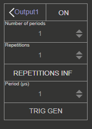
Number of periods (NCYC): Number of signal periods in one burst. Also known as Number of Cycles (NCYC).
Repetitions (NOR): Number of repeated bursts. Also known as Number Of Repetitions (NOR).
REPETITIONS INF: When selected, the burst signals are repeated indefinitely.
Period (μs): Period between the start of the first burst and the start of the next burst. Burst will always have a minimum of 1 μs between them.
TRIG GEN: Manually trigger the signal generator.
Sweep Mode
Configure the output to operate in sweep mode. All other settings, except frequency are kept from the Continuous mode (the higher menu). The sweep mode will stay active until turned OFF or the settings are RESET to defaults. Here are the available settings:
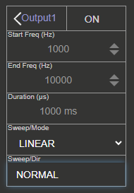
Start Freq (Hz): Sweep start frequency in Hertz.
End Freq (Hz): Sweep end/stop frequency in Hertz.
Duration (μs): Sweep duration in microseconds. When operating in UP-DOWN direction, this is applies to both directions (if set to 1000 ms, the sweep will take 1000 ms in the UP direction and then 1000 ms in the DOWN direction).
Sweep Mode: Sweep mode. Either LINEAR or LOG.
Sweep Dir: Sweep direction. Either NORMAL or UP-DOWN.
Trigger
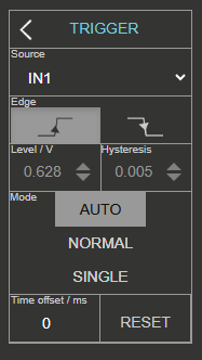
The trigger is used to enable the scope to display changing waveforms on the scope screen in a steady fashion. Here are the available settings:
Source: The trigger source can be input channel 1 (IN1), input channel 2 (IN2), or an external source. On the STEMlab 125-14 4-Input the trigger source can also be set to input channel 3 (IN3), or input channel 4 (IN4).
Edge: During the time sweep (acquisition), signal amplitude can cross the trigger level from a higher value to a lower one or vice versa. The edge setting determines in which case the trigger condition is set to “true”.
Level/V: The trigger level value is used to determine at which value of signal amplitude the trigger condition is satisfied (true). When signal amplitude achieves or crosses this value, the trigger state is set to “true”. Following the “true” trigger condition, the acquisition and signal plotting will be executed.
Hysteresis/V: Minimal jump in voltage around the trigger level that can create another trigger condition. Used to prevent the noise from creating additional triggers if the signal amplitude is close to the trigger level.
Mode: Oscilloscope trigger mode
AUTO Trigger state and conditions are disregarded. Signal acquisition and signal trace re-plotting are executed in a repetitive (continuous) manner. This is the default setting.
NORMAL The acquisition (trace (re)plotting) is executed only if the trigger state is “true”. In other words, the signal needs to satisfy the trigger condition to be acquired and (re)plotted by the Oscilloscope.
SINGLE After trigger condition is satisfied by the observed signal, the acquisition is executed only once, and trace re-plotting is stopped regardless of the repetitive “true” trigger states.
Time offset/ms: Trigger time offset. This setting moves the time-offset cursor on the screen. Determines the trigger location on the Oscilloscope screen.
RESET: Resets time offset back to 0 ms (middle of screen).
The Source parameter defines the source used for this purpose. With the IN1, IN2, IN3, or IN4, the signal at the respective input is selected; with the EXT, you can invoke the trigger from outside through:
DIO0_P pin on the E1 connector.
BNC connector on the front panel (only SIGNALlab 250-12).
Math
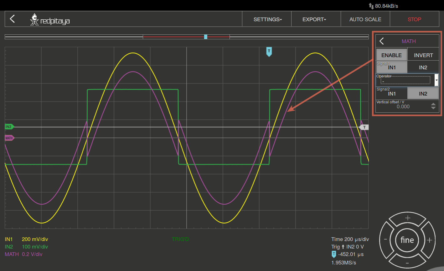
Among the more interesting features of a digital oscilloscope is the “math” channel. The available settings are the following:
+ Add the selected channels.
- Subtract the selected channels.
* Multiply selected channels.
ABS Give an absolute value of the selected signal.
dy/dt Give a time derivation of the selected signal.
ydt Give a time integration of the selected signal.
INVERT Invert the signal.
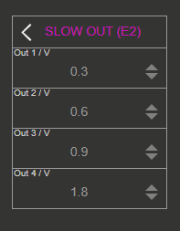
Out/E2
Control the voltage on the slow analog outputs. Type in the value in Volts into the field labeled by the slow analog output number.
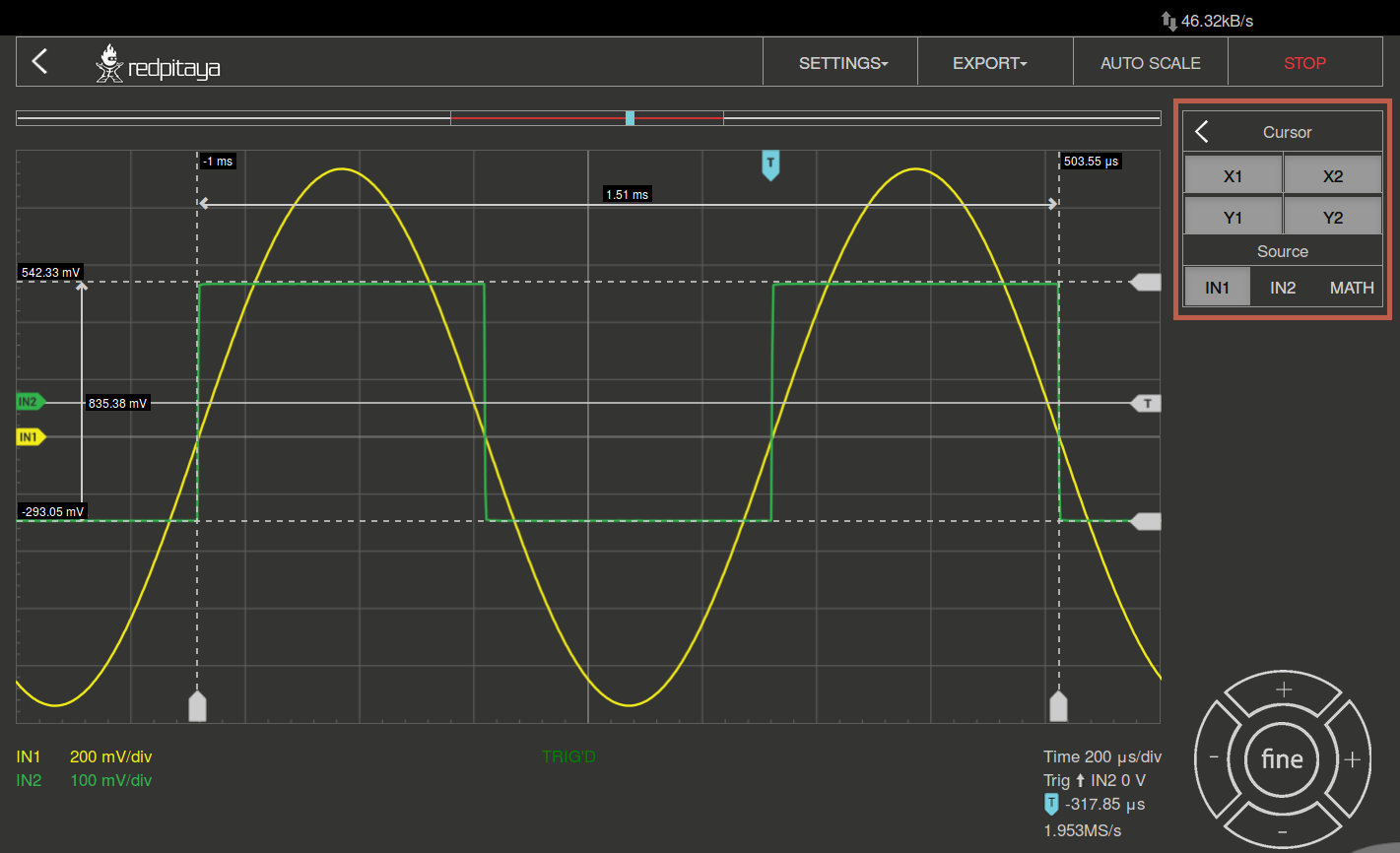
Cursor
This feature enables the user to easily get the data of relevant basic measurements, such as signal period, amplitude, time delay, amplitude difference between two points, time difference between two points, etc. The cursors can be moved by clicking and dragging them on the screen.
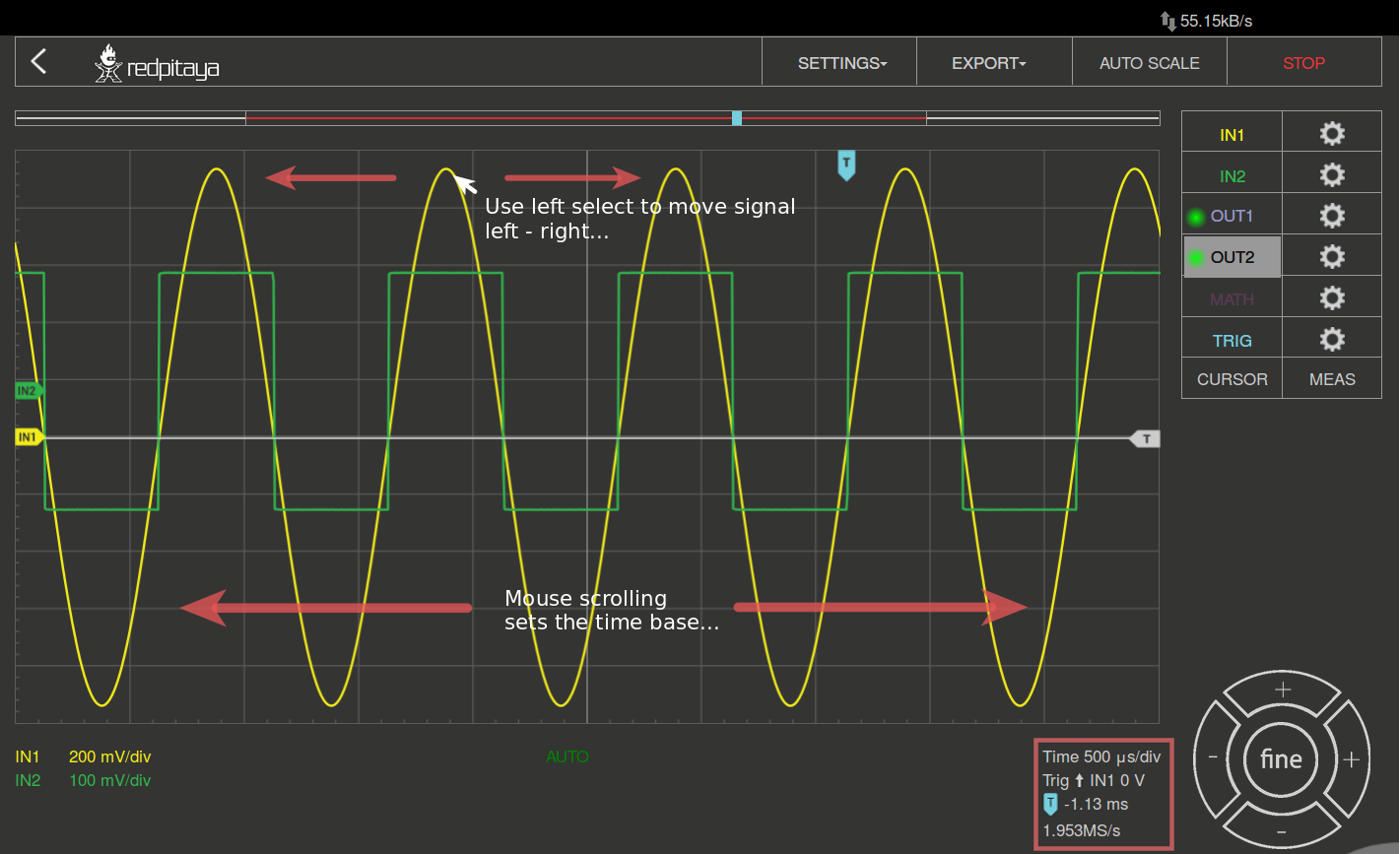
Navigate
When you have a lot of data to analyse, it is very important to get through it easily. Navigate left and right by dragging the data where you want and effortlessly zooming in and out by using your mouse scroll wheel.
Tip
Shift + scroll wheel while a channel is selected scales the signal along the Y-axis (voltage scale) for that channel only.
Clicking a cursor on the left side of the screen sets that channel as the active channel.
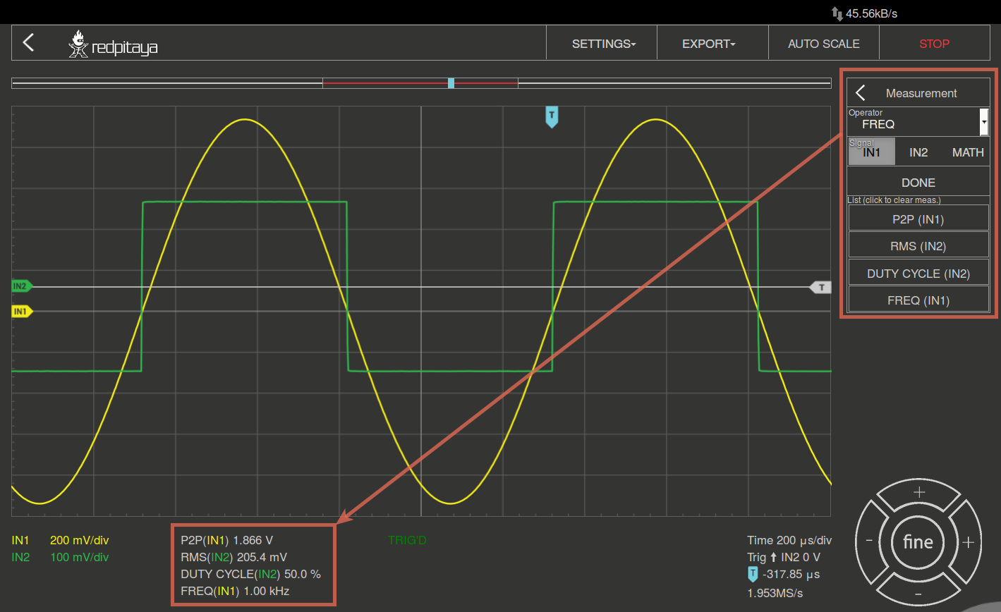
Measurements
The menu can be found under the MEAS button. Here you can select up to 4 measured values in total and then provide the corresponding values. In the Operator field, select the desired measurement and then set the signal from which channel the value should be taken. One-click on DONE shows the value at the bottom of the channel settings. You may choose among the following:
P2P: The difference between the lowest and the highest measured voltage value.
MEAN: The signal’s calculated average.
MAX: The maximum voltage value measured.
MIN: The lowest voltage value measured.
RMS: The calculated RMS (root mean square) of the signal.
DUTY CYCLE: The signal’s duty cycle (ratio of the pulse duration and period length).
PERIOD: Displays the period length, the time length of vibration.
FREQ: The frequency of the signal.
The measurements are removed by clicking on the specific measurement from the list.
Specifications
Oscilloscope
STEMlab 125-14 |
STEMlab 125-14 4-Input |
SDRlab 122-16 |
SIGNALlab 250-12 |
STEMlab 125-10 (discontinued) |
|
|---|---|---|---|---|---|
Input channels |
2 |
4 |
2 |
2 |
2 |
Bandwidth |
50 MHz |
50 MHz |
300 kHz - 50 MHz |
60 MHz |
40 MHz |
Resolution |
14 bit |
14 bit |
16 bit |
12 bit |
10 bit |
Memory depth |
16k samples |
16k samples |
16k samples |
16k samples |
16k samples |
Input range |
±1 V (LV) and ±20 V (HV) [1] |
±1 V (LV) and ±20 V (HV) [1] |
±0.25 V / -2 dBm |
±1 V / ±20 V [2] |
±1 V (LV) and ±20 V (HV) [1] |
Input coupling |
DC |
DC |
AC |
AC/DC [2] |
DC |
Minimal Voltage Sensitivity |
±0.122mV / ±2.44mV |
±0.122mV / ±2.44mV |
±7.6uV |
±0.488mV / ±9.76mV |
± 1.95mV / ± 39mV |
External Trigger |
E1 connector (DIO0_P) |
E1 connector (DIO0_P) |
E1 connector (DIO0_P) |
BNC trigger connector |
E1 connector (DIO0_P) |
Input impedance |
1 MΩ |
1 MΩ |
50 Ω |
1 MΩ |
1 MΩ |
Signal generator
STEMlab 125-14 |
STEMlab 125-14 4-Input |
SDRlab 122-16 |
SIGNALlab 250-12 |
STEMlab 125-10 (discontinued) |
|
|---|---|---|---|---|---|
Output channels |
2 |
N/A |
2 |
2 |
2 |
Frequency Range |
0 - 50 MHz |
N/A |
300 kHz - 60 MHz |
0 - 60 MHz |
0 - 50 MHz |
Resolution |
14 bit |
N/A |
14 bit |
12 bit |
10 bit |
Signal buffer |
16k samples |
N/A |
16k samples |
16k samples |
16k samples |
Output range |
±1 V |
N/A |
±0.25 V/ -2 dBm (50 Ω load) |
±1 V / ±5 V (into 50 Ω load) [2] ±2 V / ±10 V (High-Z load) [2] |
±1 V |
Coupling |
DC |
N/A |
AC |
AC/DC [2] |
DC |
Output load |
50 Ω |
N/A |
50 Ω |
50 Ω / High-Z [2] |
50 Ω |
Source code
The Oscilloscope and Signal Generator source code is available on our GitHub.