3.2.11. Vector Network Analyzer
Note
The VNA application is a 3rd party application created and maintained by Pavel Demin and the SDR community. The application in the official Red Pitaya OS is ported from the community Alpine Linux image. For the access to the latest community updates, please check the Pavel Demin's Red Pitaya Notes VNA page.
What do I need before I start?
VNA application requirements:
Windows or Linux-based personal computer (PC).
The following accessories and materials are available in the Red Pitaya store:
any kit that includes a STEMlab 125-14, SDRlab 122-16, or 125-10 (discontinued) board
Vector Network Analyzer bridge module
Start using Red Pitaya as a Vector Network Analyser
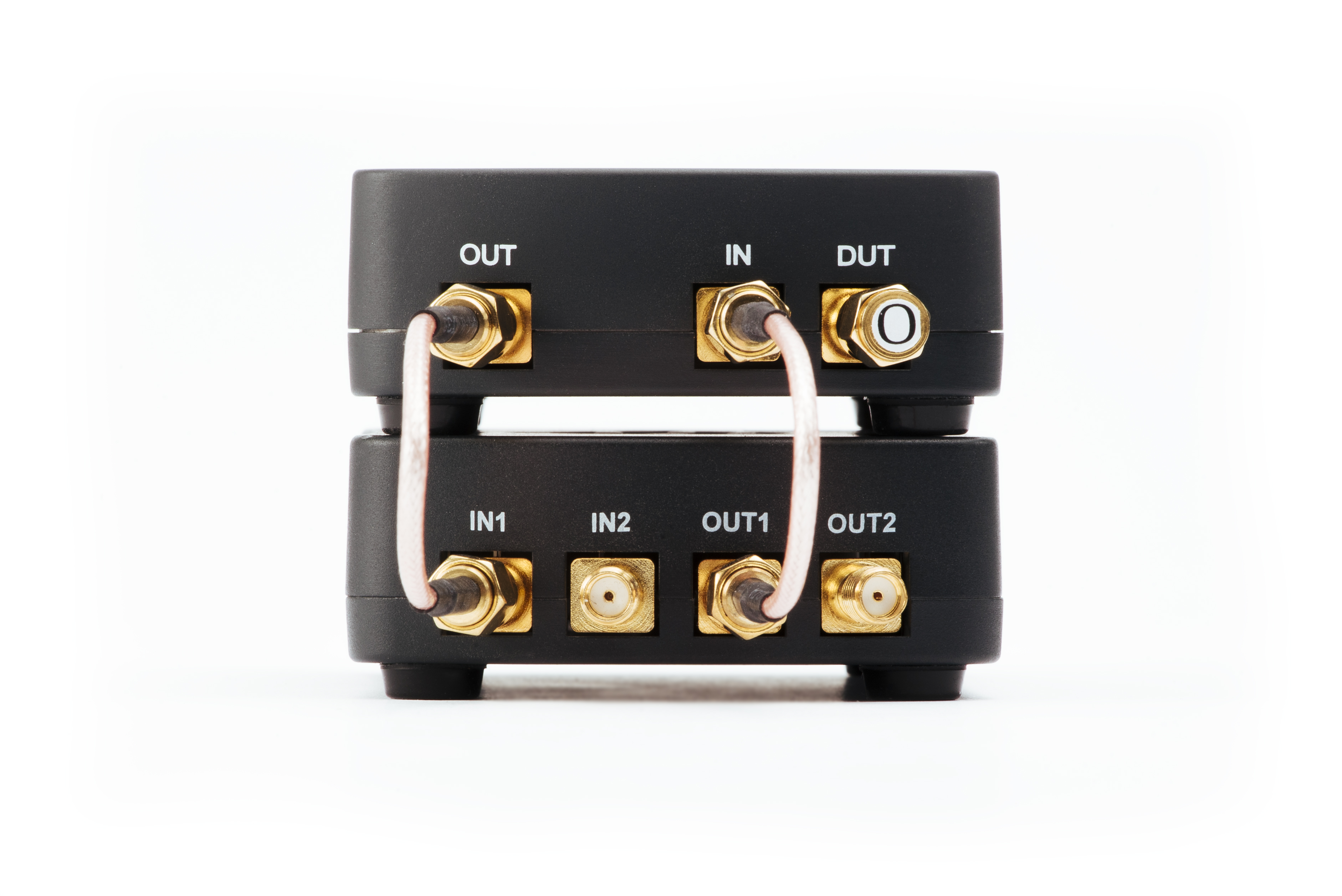
Connect Vector Network Analyzer bridge to the Red Pitaya
Connect the VNA module’s OUT to the Red Pitaya IN1
Connect the VNA module’s IN to the Red Pitaya OUT1.
Set the IN1 jumpers on the Red Pitaya to the LV position.

Install & run network Vector Network Analyzer control app
Windows users only
Open the VNA application
Download and unpack the Windows control client.
Run the
vna.exeprogram located in the control directory.Type in the IP address of the Red Pitaya board and press the Connect button.
Perform calibration and measurements.
Note
To get access to the latest community version of the VNA, please check out Pavel Demin's Red Pitaya Notes VNA page. The installation instructions differ only slightly:
Open the VNA application
Head to Pavel Demin's Red Pitaya Notes VNA page. There you can read more about the inner workings of the application as well as find links to other useful information.
Find the Getting started with MS Windows section and follow the bullet points. SKIP the first three points if you are using official Red Pitaya OS!
Download and unpack the release zip folder from the link above to your computer.
Run the
vna.exeprogram located in the control directory.Type in the IP address of the Red Pitaya board and press the Connect button.
Perform calibration and measurements.
Linux users only
Open the VNA application
Download and unpack the Linux control client.
Install Python 3 and all the required libraries:
sudo apt-get install python3-dev python3-pip python3-numpy python3-pyqt5 libfreetype6-dev
sudo pip3 install matplotlib mpldatacursor
Run the control program:
cd /vna/client
python3 vna.py
Type in the IP address of the Red Pitaya board and press the Connect button.
Perform calibration and measurements.
Note
To get access to the latest community version of the VNA, please check out Pavel Demin's Red Pitaya Notes VNA page. The installation instructions differ only slightly:
Open the VNA application
Head to Pavel Demin's Red Pitaya Notes VNA page. There you can read more about the inner workings of the application as well as find links to other useful information.
Find the Getting started with GNU/Linux section and follow the bullet points. SKIP the first three points if you are using official Red Pitaya OS!
Install Python 3 and all the required libraries:
apt-get install python3-numpy python3-matplotlib python3-pyqt5Clone the source code repository to your computer:
git clone https://github.com/pavel-demin/red-pitaya-notesRun the control program:
cd red-pitaya-notes/projects/vna/client
python3 vna.py
Type in the IP address of the Red Pitaya board and press the Connect button.
Perform calibration and measurements.
Type in the IP or URL address of the Red Pitaya board
Connect by entering the Red Pitaya’s IP:
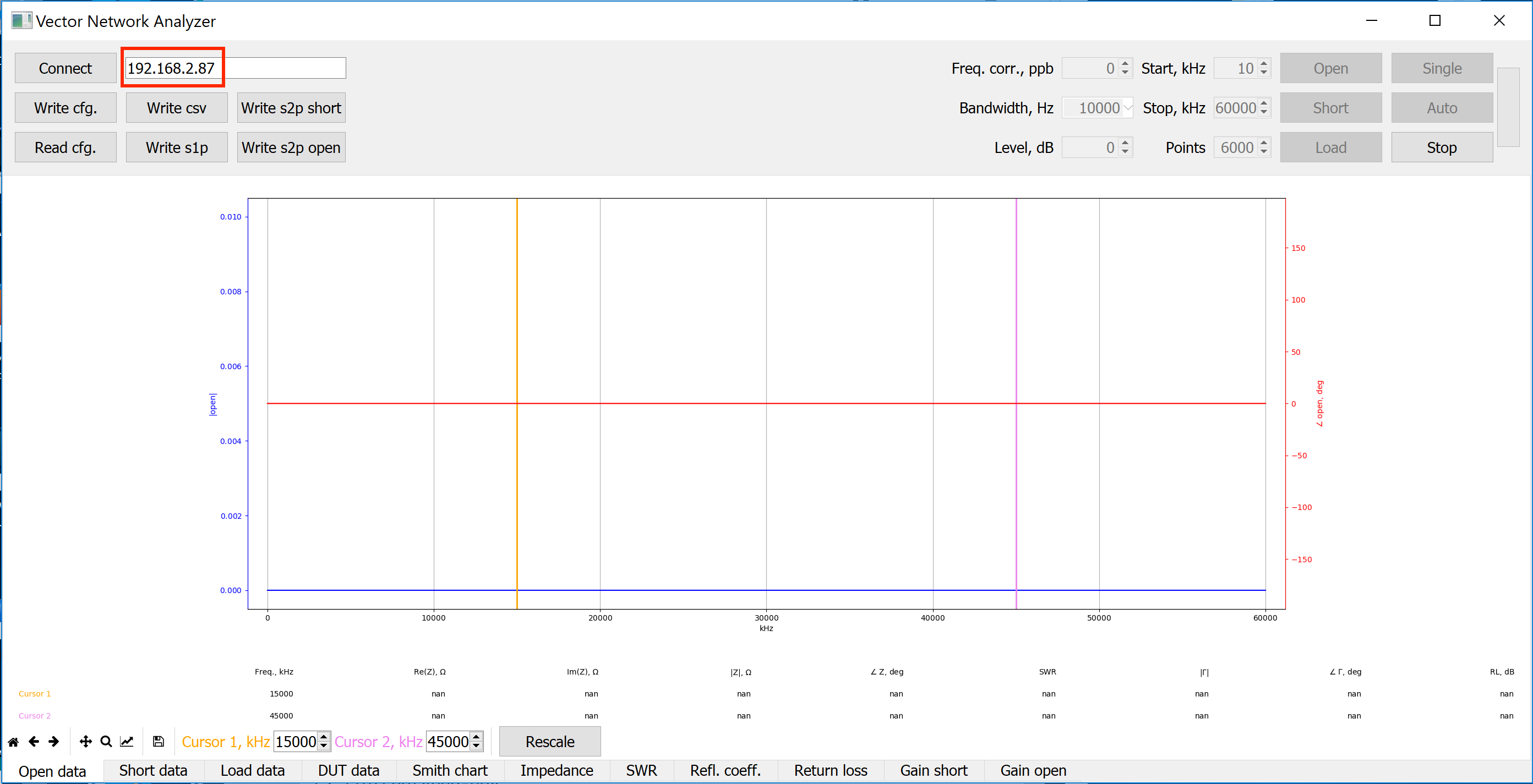
To find the IP address of your Red Pitaya board, first connect to Red Pitaya by following these instructions.
Then go to System->Network Manager. The IP is written next to the label. Address: xxx.xxx.xxx.xxx .
Connect by entering RedPitaya URL:

Run the Vector Network Analyzer application on the Red Pitaya
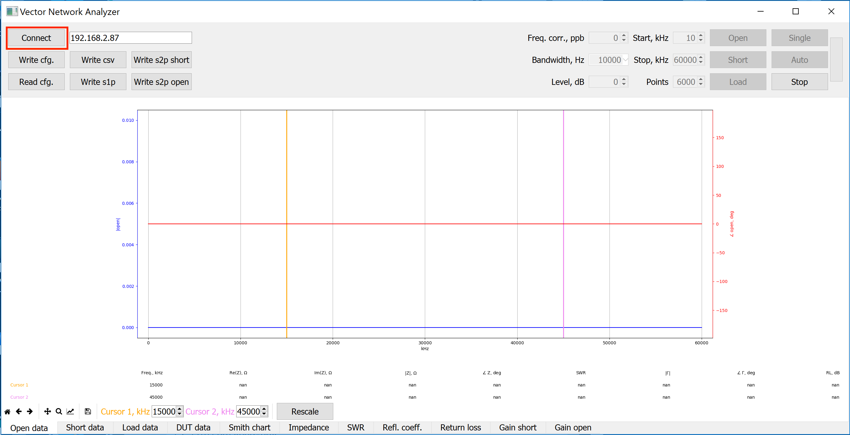
Click “Connect” inside the Vector Network Analyzer control app
Perform calibration and start measuring
Note
On SDRlab 122-16 the VNA module works for frequencies above 500 kHz. Please start the calibration process at 500 kHz (ignore calibration values in the pictrures).
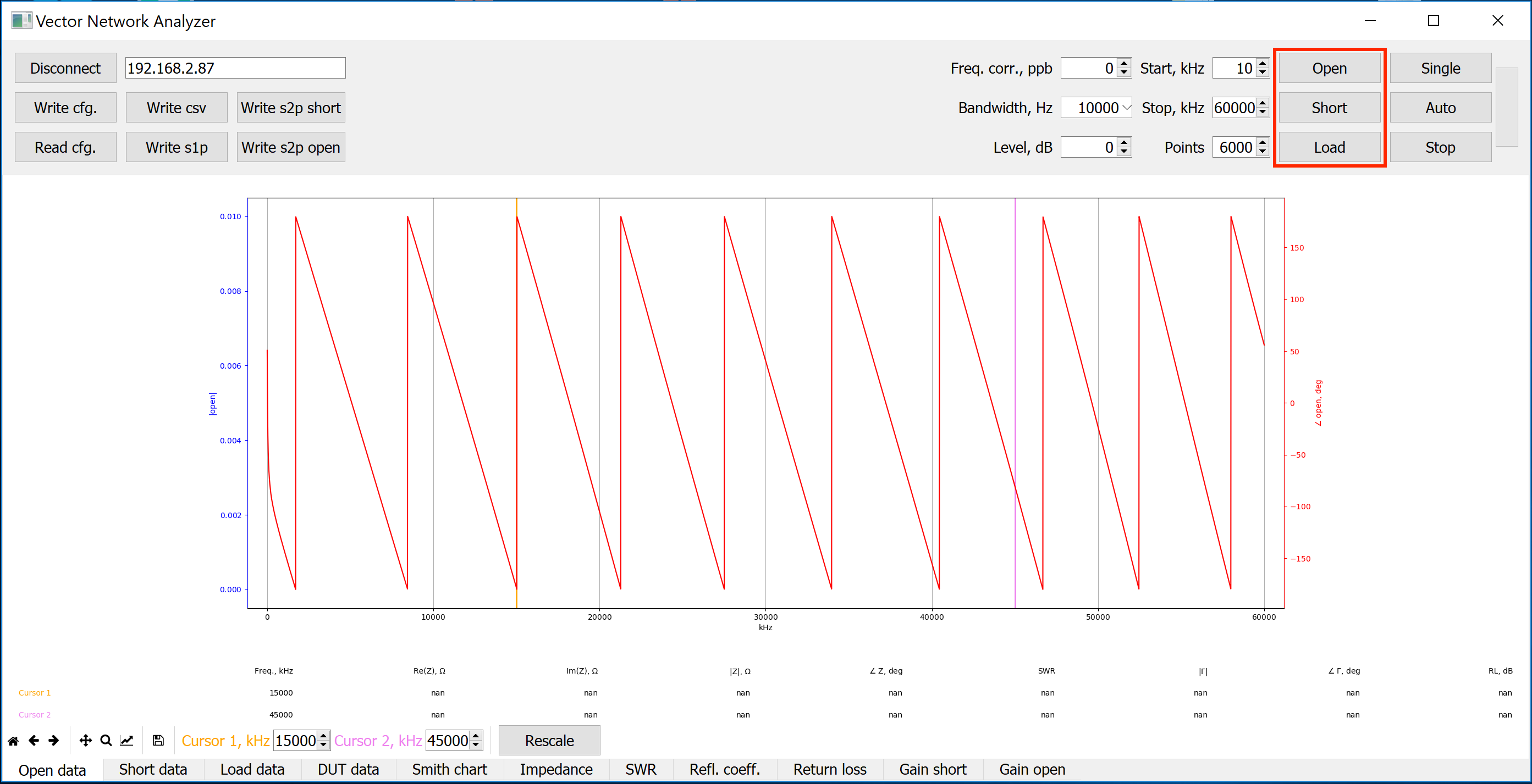
Connect the SMA OPEN calibration connector marked with the letter O to the DUT SMA connector of the network vector analyzer bridge module. Click the button “Open” and wait for the calibration procedure to complete.
Connect the SMA SHORT calibration connector marked with the letter S to the DUT SMA connector of the network vector analyzer bridge module. Click the button “Short” and wait for the calibration procedure to complete.

Connect the SMA LOAD calibration connector marked with the letter L to the DUT SMA connector of the network vector analyzer bridge module. Click the button “Load” and wait for the calibration procedure to complete.

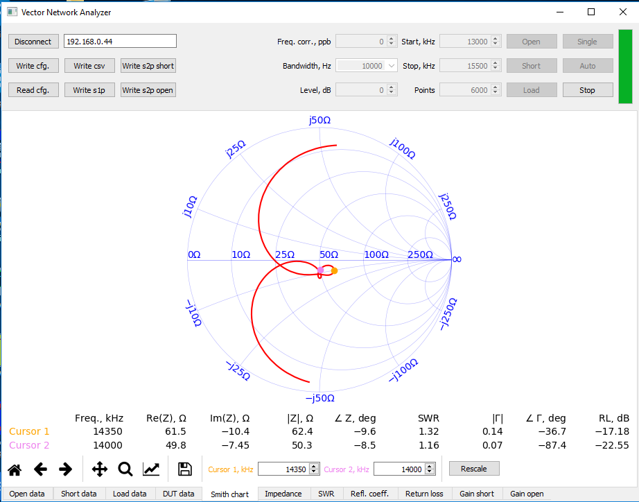
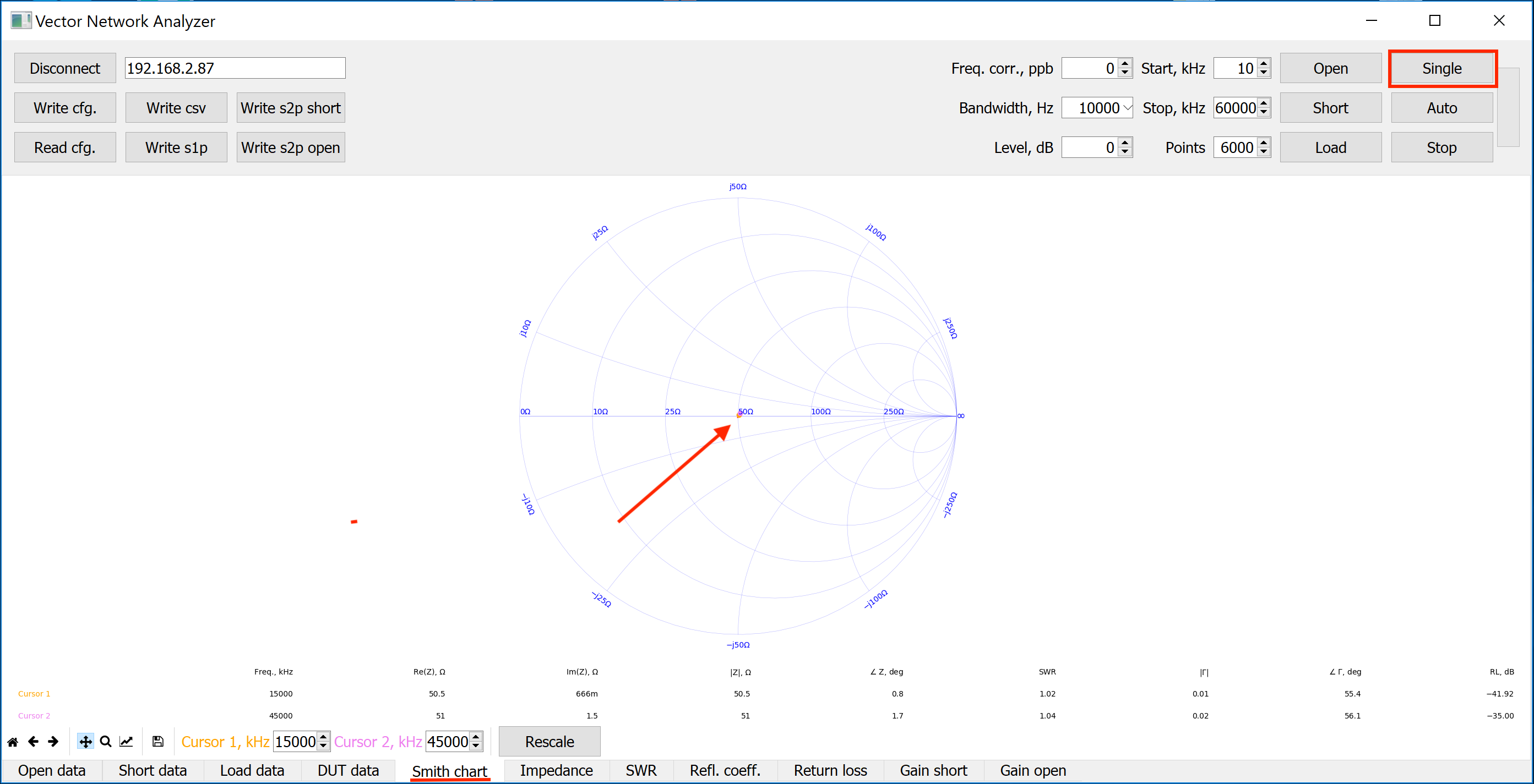
Select the Smith chart tab at the bottom and then click the Single button to perform a single measurement of the DUT. A dot in the middle of the Smith chart circle (@ 50 Ohm) will indicate that VNA is properly measuring the reference 50 Ohm LOAD.
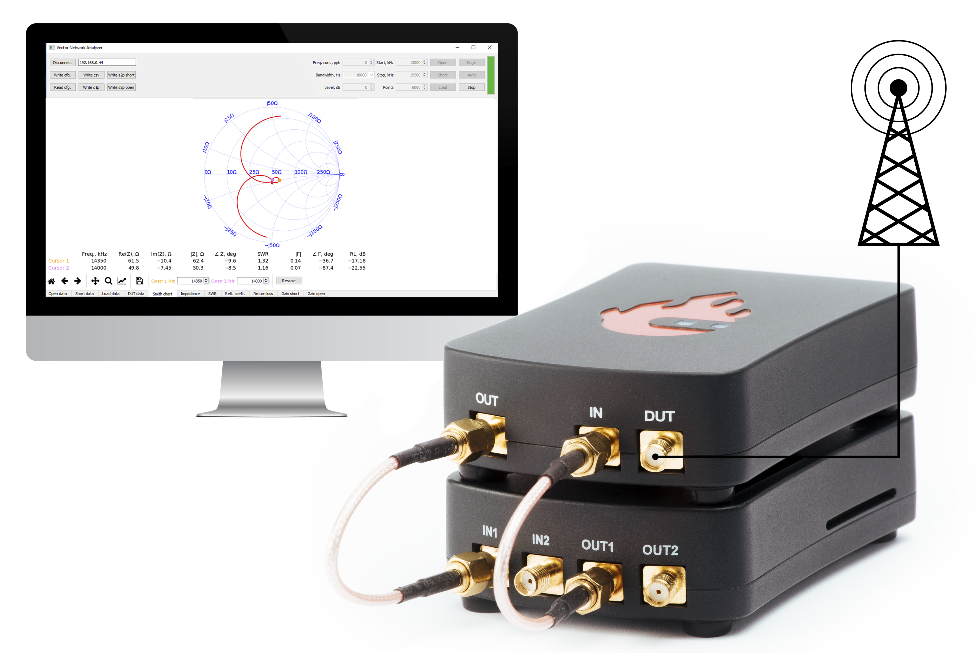
Disconnect the LOAD SMA connector and connect whatever DUT you’d like to measure.
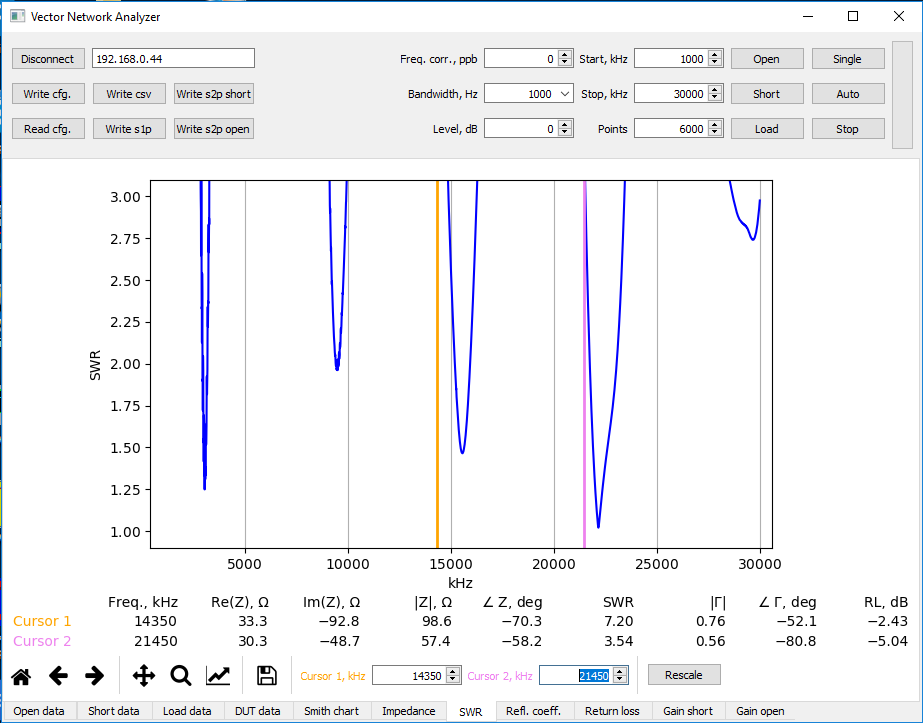
Examples:
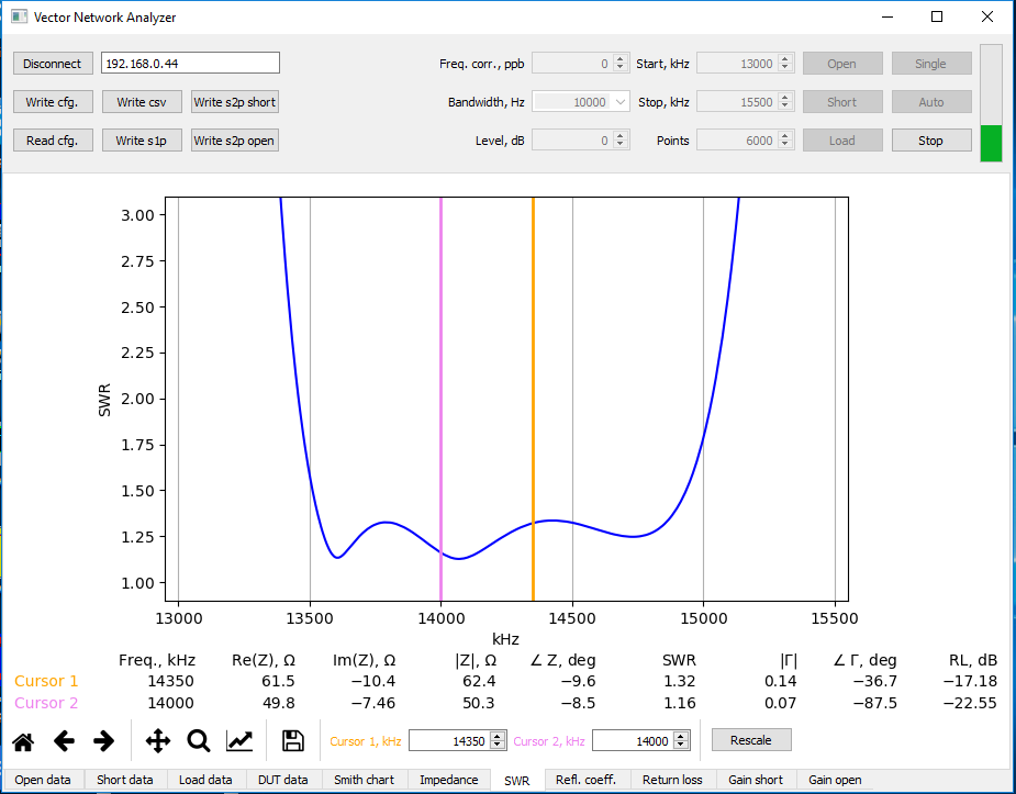
- Measurement of a 21-meter vertical antenna
The antenna is not properly tuned (at frequency 14, 21 MHz, SWR should be = 1.5).
- 20-meter bandpass filter for HAM RADIO
SWR is better than 1.5 between the start and stop band frequencies, and the filter load is around 50 Ohm.