3.4. Multiboard Synchronisation
Multiboard synchronisation is a feature that allows you to synchronise clock and trigger signals across multiple Red Pitaya boards to achieve a higher number of fast analog channels for acquisition or generation.
There are two ways to achieve clock and trigger synchronisation across multiple Red Pitaya boards:
Red Pitaya X-Channel System 2.0 (Click Shield) - Multiple External clock Red Pitaya boards synchronised with Click Shields using dedicated ZL40213 LVDS clock fanout buffers. Provides optimal signal integrity across extended daisy chains with minimal clock and trigger jitter.
Red Pitaya X-Channel System - One primary and multiple secondary Red Pitaya boards connected in a daisy chain with SATA (Original Gen) or USB-C (Gen 2) cables. Cost-effective solution ideal for 2-3 board systems at moderate to high sampling rates.
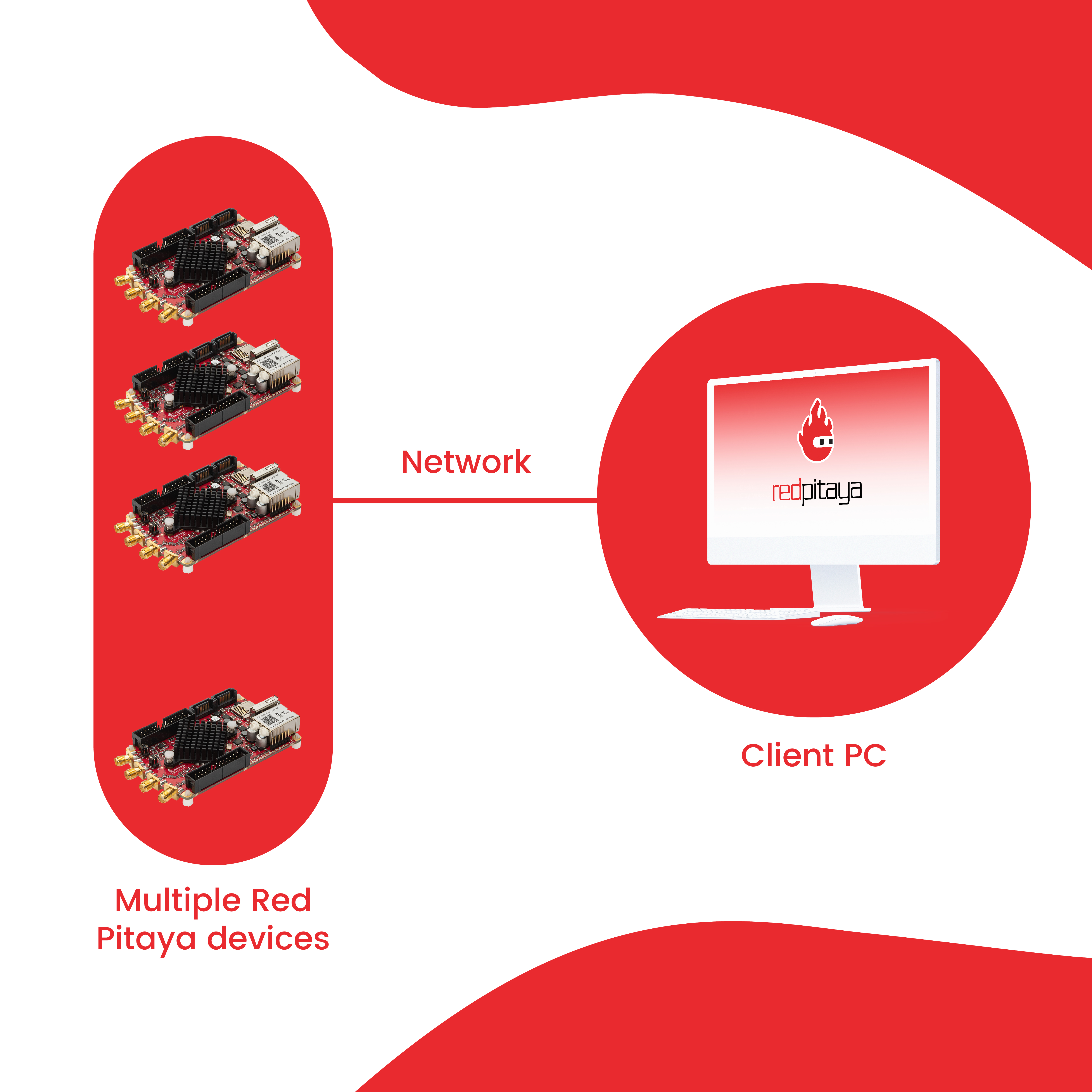
The synchronized boards can be controlled as any normal Red Pitaya board. However, remote control from a computer is usually preferred as it allows for more flexibility and easier control of multiple boards from the same program.
For detailed comparison of the two systems, please see the Q&A section.
Note
Multichannel generation is currently still in development and is not yet fully supported.
Note
For streaming application multiboard setup (network configuration, client detection, bandwidth considerations), see the Multiboard Streaming documentation.
3.4.1. How can I control synchronised boards?
C++ & Python API commands (harder to configure as a program must be executed on each board separately).
Streaming application (either Desktop client application or command line client).
Note
Any restrictions or limitations of applications and control methods also apply to multiboard synchronisation. However, these should be interpreted per board and not for the full system. For example, if the Data stream control application has an input data limitation of 20 MB/s per board (OS 2.05-37) and we have three boards in the system, the total input data rate is 60 MB/s (20 MB/s per board).
3.4.2. X-Channel System 2.0 (Click Shield) Synchronisation
Red Pitaya Click Shields enable high-performance clock and trigger synchronisation between multiple Red Pitaya units or other devices using dedicated ZL40213 LVDS clock fanout buffers. This professional-grade clock distribution solution maintains optimal signal integrity and minimal jitter regardless of daisy chain length.
Ideal for:
Large multi-board systems: 4+ boards with consistent performance across the entire chain
Maximum sampling rates: Maintains signal quality at highest acquisition speeds
Minimal jitter requirements: Applications demanding precise timing across all boards
Extended daisy chains: Signal integrity maintained regardless of chain length
Mixed device systems: Can integrate other external clock devices via U.FL connections
Key advantages:
Dedicated clock buffers: ZL40213 LVDS fanout buffer maintains sharp clock edges throughout the chain
Minimal signal degradation: Professional-grade clock distribution ensures clean signals at all sampling rates
No cumulative signal degradation: Clock buffer at each stage prevents signal quality loss
Low jitter performance: Precise timing with minimal drift across all boards
Custom external clock support: Enables connection of custom external clock sources to the daisy chain via U.FL cables
Note
The clock and trigger synchronisation with Click Shields is available only with Red Pitaya board models that can accept an external clock (External clock models, STEMlab 125-14 4-Input and Pro versions of Gen 2 boards). Please see the Click Shield compatibility section for more information.
Setup
The Red Pitaya Click Shields can synchronise multiple external clock Red Pitaya units together. As U.FL cables are used for clock and trigger synchronisation, other external clock devices can also be included in the chain. The connection provides minimal clock signal delay between multiple Red Pitaya units, as there is only a single ZL40213 LVDS clock fanout buffer between two units.
To synchronise two or more external clock Red Pitaya units, establish the following connections with U.FL cables between the primary board (transmitting clock and trigger signals) and the secondary board (receiving the clock and trigger signals). Use one of the two schemes depending on whether you want to connect an external clock or use the oscillator on the Red Pitaya Click Shields. Use the configuration for the secondary board for any additional boards in the chain.
Oscillator

When using the oscillator, the first Red Pitaya Click Shield transmits the clock and trigger signals to all devices in the chain. Here are the most important things to check:
Primary board:
Jumpers J4 and J5 connected. Connect the oscillator to the clocking transmission line.
Jumpers J6 and J7 connected. Connect the Red Pitaya trigger to the trigger transmission line.
Jumper J1 disconnected (unless using a single wire clock).
CLK OSC switch in ON position.
CLK SELECT switch in EXT position.
Secondary board:
Jumper J6 connected. Connect the trigger to the Ext. trigger pin.
Jumper J1 disconnected (unless using a single wire clock).
CLK OSC switch in OFF position.
CLK SELECT switch in EXT position.
If an external trigger signal is used, copy the secondary board’s trigger connections to the primary board (disconnect J7 and connect the external trigger U.FL cable). Otherwise, DIO0_N acts as external trigger output (on the primary board), and DIO0_P acts as external trigger input.
External Clock

When using an external clock and external trigger, the clock and trigger signals are transmitted to all devices in the chain. All the Click Shields share the same configuration:
Primary and Secondary boards:
Jumper J6 connected. Connect the trigger to the Ext. trigger pin.
Jumper J1 disconnected (unless using a single wire clock).
CLK OSC switch in OFF position.
CLK SELECT switch in EXT position.
External clock type:
According to the datasheet the ZL40213 fanout buffer supports a wide range of differential or single-ended input clock signals:
LVPECL
LVDS
CML
HSTL
LVCMOS
For more information on the external clock signal, please check the ZL40213 datasheet. The inputs are in the AC coupling configuration. The chip is powered by a 3V3 power supply.
Hardware specifications
For more information on the Click Shield, please see the Click Shield documentation.
3.4.3. X-Channel Synchronisation
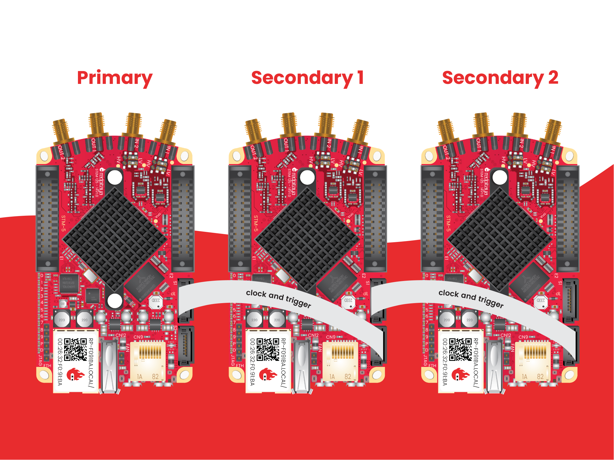
The Red Pitaya X-Channel System provides clock and trigger synchronization between multiple Red Pitaya boards using a daisy-chain topology with SATA (Original Gen) or USB-C (Gen 2) cables. The system routes clock and trigger signals sequentially through each board’s FPGA, making it a cost-effective solution that requires no additional synchronization hardware.
The X-Channel System consists of one primary device and one or more secondary devices connected in a daisy chain.
Ideal for:
Small to medium systems: 2-3 boards where signal quality remains excellent
Moderate to high sampling rates: Performance is comparable to X-channel 2.0 (Click Shield) synchronisation
Cost-effective setups: No additional synchronization hardware required beyond cables
Quick deployment: Simple cable connections between boards without external components
Full GPIO access: All GPIO pins remain available for user applications
Technical characteristics:
Clock synchronization: All boards share a common clock sourced from the primary board
Trigger synchronization: Synchronized acquisition start from the primary board
Phase alignment: Data from all boards is phase-aligned
Signal routing: Clock and trigger signals propagate through each board’s FPGA in sequence
Note
For larger systems (4+ boards) or applications requiring maximum sampling rates across many boards, the X-channel 2.0 (Click Shield) synchronisation provides dedicated clock buffers that maintain optimal signal integrity throughout longer daisy chains.
Note
We have decided to use primary and secondary device terminology instead of the standard master and slave device.
Setup
The Red Pitaya X-Channel system includes two types of devices:
one STEMlab 125-14 Pro Gen 2 primary device.
one or more STEMlab 125-14 Pro Gen 2 secondary devices denoted by an “S” sticker.
Both devices must be one of the Pro board models (STEMlab 125-14 Pro Gen 2, STEMlab 125-14 Pro Z7020 Gen 2).
one STEMlab 125-14 primary device (STEMlab 125-14 Low Noise).
one or more STEMlab 125-14 Low Noise secondary devices denoted by an “S” sticker.
S1 and S2 connectors are used to connect the primary and secondary devices:
S1 - output for clock and trigger signals.
S2 - input for (external) clock and trigger signals.
In order to achieve synchronization, the primary device outputs its clock and trigger signals through the S1 connector. The cable connection should therefore connect S1 connector of the primary device with S2 connector of the secondary device. To continue the daisy chain, connect the S1 connector of the first secondary device to the S2 connector of the second secondary device, and so on.
It should be noted that the secondary devices differ from the primary device hardware-wise. The secondary devices are a special type of external clock Red Pitaya that receives the clock signal from the “FPGA”.
Cable orientation
The S1 and S2 connectors are SATA connectors on boards and USB-C connectors on Gen 2 boards. Usually, USB-C cables are bipolar and can be connected in either direction, however, the S1 and S2 connectors are meant for sharing the clock and trigger signals and not connecting external devices. Therefore, the orientation of the cable is important. On Gen 2 boards, two LEDs (L - Link and O - Orientation) are located next to the S1 connector:
The O LED indicates the orientation of the cable.
The L LED indicates whether the connection between the boards was successfully established.
When connecting the boards, make sure both LEDs are lit. If the O LED is not lit, change the orientation of the cable.
Note
Booting secondary units without the external clock present? The official Red Pitaya OS will not boot on the secondary units without providing an external clock as it relies on reading the FPGA register map, which is available if the ADC clock is present. However, by modifying the software, the Linux OS itself can boot even without the external clock present, but please note it will crash when trying to read from the FPGA without the external clock present.
Note
We recommend using OS 2.00-23 or higher for the X-channel system.
With 2.00 OS both the primary and the secondary devices use the SAME OS!
With 1.04 OS the primary and secondary boards use DIFFERENT OS!
Alternative uses of S1 and S2 connectors
The S1 and S2 connectors can also be used to connect to external devices directly to the FPGA. On original generation boards where SATA connectors are used, this is slightly easier as the connectors are standard SATA. Gen 2 presents a challenge as the S1 and S2 connectors do not support the USB-C standard.
In either case, connecting external devices to the S1 and S2 connectors requires a modification in the FPGA as the default firmware does not support this feature.
For more information on using S1 and S2 connectors for external devices, please see the FPGA development documentation and consult the hardware schematics for the specific board model.
Board compatibility
The X-channel synchronisation is out-of-the-box compatible with the following Red Pitaya board models:
Primary devices (standard boards):
Secondary devices (require special hardware modification):
Warning
Secondary devices are NOT standard Red Pitaya boards. They require factory hardware modifications to receive the clock signal from the primary device through the FPGA. Secondary boards are marked with an “S” sticker and must be specifically ordered or modified at the factory.
Standard Red Pitaya boards cannot be used as secondary devices without hardware modification by Red Pitaya.
Secondary devices based on the compatible board models listed above are available from Red Pitaya and are essential for building X-channel systems.
Boards with connectors but no X-channel support:
Board models like STEMlab 125-14 4-Input and SDRlab 122-16 have S1/S2 connectors, but the hardware itself does not allow for sharing the clock signal through these connectors. These boards cannot be used in X-channel configurations.
Example - signal acquisition (streaming client)
Simultaneous acquisition of 6 input signals.
In this example, we will acquire data from three synchronised Red Pitaya units (X-channel system), which gives us a total of six RF input channels. For client installation and usage, please see the Streaming application documentation.
PRIMARY_IP=192.168.2.141, SECONDARY1_IP=192.168.2.60 SECONDARY2_IP=192.168.2.25
Open the streaming app on all Red Pitaya boards (primary and secondary) via the web interface.
Adjust the streaming mode and settings. For more information on specific settings check the Streaming Configuration.
rpsa_client.exe -c -h 192.168.2.141,192.168.2.60,192.168.2.25 -s F -f test.conf -v

2022.06.02-15.20.21.173:  Connected: 192.168.2.141
2022.06.02-15.20.21.176:  Connected: 192.168.2.25
2022.06.02-15.20.21.178:  Connected: 192.168.2.60
2022.06.02-15.20.21.278:  Send configuration to: 192.168.2.141
2022.06.02-15.20.21.291:  Send configuration to: 192.168.2.25
2022.06.02-15.20.21.291:  SET: 192.168.2.141 [OK]
2022.06.02-15.20.21.303:  Send configuration to: 192.168.2.60
2022.06.02-15.20.21.309:  Send configuration save command to: 192.168.2.141
2022.06.02-15.20.21.324:  SET: 192.168.2.25 [OK]
2022.06.02-15.20.21.332:  Send configuration save command to: 192.168.2.25
2022.06.02-15.20.21.337:  SET: 192.168.2.60 [OK]
2022.06.02-15.20.21.343:  Send configuration save command to: 192.168.2.60
2022.06.02-15.20.21.350:  SAVE TO FILE: 192.168.2.141 [OK]
2022.06.02-15.20.21.357:  SAVE TO FILE: 192.168.2.25 [OK]
2022.06.02-15.20.21.363:  SAVE TO FILE: 192.168.2.60 [OK]
Start the X-channel streaming of 6 inputs.
--streaming --host PRIMARY IP, SECONDARY1 IP, SECONDARY2 IP, --format=wav --dir=NAME
--limit=SAMPLES

rpsa_client.exe -s -h 192.168.2.141,192.168.2.60,192.168.2.25 -f wav -d ./acq -l 10000000 -v

2022.06.02-15.25.00.795:  Connected: 192.168.2.141
2022.06.02-15.25.00.798:  Connected: 192.168.2.25
2022.06.02-15.25.00.804:  Connected: 192.168.2.60
2022.06.02-15.25.00.907:  Send stop command to master board 192.168.2.141
2022.06.02-15.25.00.925:  Streaming stopped: 192.168.2.141 [OK]
2022.06.02-15.25.01.32:  Send stop command to slave board 192.168.2.25
2022.06.02-15.25.01.36:  Send stop command to slave board 192.168.2.60
2022.06.02-15.25.01.37:  Streaming stopped: 192.168.2.25 [OK]
2022.06.02-15.25.01.45:  Streaming stopped: 192.168.2.60 [OK]
2022.06.02-15.25.01.156:  Send start command to slave board: 192.168.2.25
2022.06.02-15.25.01.169:  Send start command to slave board: 192.168.2.60
2022.06.02-15.25.01.286:  Streaming started: 192.168.2.25 TCP mode [OK]
2022.06.02-15.25.01.307:  Streaming started: 192.168.2.60 TCP mode [OK]
2022.06.02-15.25.01.407:  Send start command to master board: 192.168.2.141
2022.06.02-15.25.01.542:  Streaming started: 192.168.2.141 TCP mode [OK]
2022.06.02-15.25.01.639:  Send start ADC command to slave board: 192.168.2.25
Run write to: ./1/data_file_192.168.2.25_2022-06-02_13-25-00.wav
Run write to: ./1/data_file_192.168.2.60_2022-06-02_13-25-00.wav
Run write to: ./1/data_file_192.168.2.141_2022-06-02_13-25-00.wav
2022.06.02-15.25.01.659:  Send start ADC command to slave board: 192.168.2.60
2022.06.02-15.25.01.660:  ADC is run: 192.168.2.25
Available physical memory: 16260 Mb
Used physical memory: 8130 Mb
Available physical memory: 16260 Mb
Used physical memory: 8130 Mb
Available physical memory: 16260 Mb
2022.06.02-15.25.01.741:  Connect 192.168.2.25
2022.06.02-15.25.01.730:  ADC is run: 192.168.2.60
Used physical memory: 8130 Mb
2022.06.02-15.25.01.752:  Connect 192.168.2.141
2022.06.02-15.25.01.764:  Connect 192.168.2.60
2022.06.02-15.25.01.826:  Send start ADC command to master board: 192.168.2.141
2022.06.02-15.25.01.834:  ADC is run: 192.168.2.141
2022.06.02-15.25.04.402:  Error 192.168.2.25
2022.06.02-15.25.04.408:  Error 192.168.2.141
2022.06.02-15.25.04.410:  Error 192.168.2.60
2022.06.02-15.25.04.415:  Send stop command to master board 192.168.2.141
2022.06.02-15.25.04.420:  Streaming stopped: 192.168.2.141 [OK]
2022.06.02-15.25.04.422:  Streaming stopped: 192.168.2.141 [OK]
2022.06.02-15.25.04.526:  Send stop command to slave board 192.168.2.25
2022.06.02-15.25.04.529:  Send stop command to slave board 192.168.2.60
2022.06.02-15.25.04.530:  Streaming stopped: 192.168.2.25 [OK]
2022.06.02-15.25.04.533:  Streaming stopped: 192.168.2.60 [OK]
2022.06.02-15.25.04.536:  Streaming stopped: 192.168.2.25 [OK]
2022.06.02-15.25.04.545:  Streaming stopped: 192.168.2.60 [OK]

2022.06.02-15.25.04.635 Total time: 0:0:2.794
=====================================================================================================================
Host              | Bytes all         | Bandwidth         |    Samples CH1    |    Samples CH2    |      Lost        |
+--------------------------------------------------------------------------------------------------------------------|
192.168.2.141     | 38.188 Mb         | 13.668 MB/s       | 10010624          | 10010624          |                  |
                  +...................+...................+...................+...................+ 0                |
                  |Lost in UDP: 0                         |Lost in file: 0                        |                  |
                  +...................+...................+...................+...................+..................|
192.168.2.25      | 38.188 Mb         | 13.668 MB/s       | 10010624          | 10010624          |                  |
                  +...................+...................+...................+...................+ 0                |
                  |Lost in UDP: 0                         |Lost in file: 0                        |                  |
                  +...................+...................+...................+...................+..................|
192.168.2.60      | 38.188 Mb         | 13.668 MB/s       | 10010624          | 10010624          |                  |
                  +...................+...................+...................+...................+ 0                |
                  |Lost in UDP: 0                         |Lost in file: 0                        |                  |
                  +...................+...................+...................+...................+..................|
=====================================================================================================================
To view acquired data, drag the .wav files from /acq to Audacity.
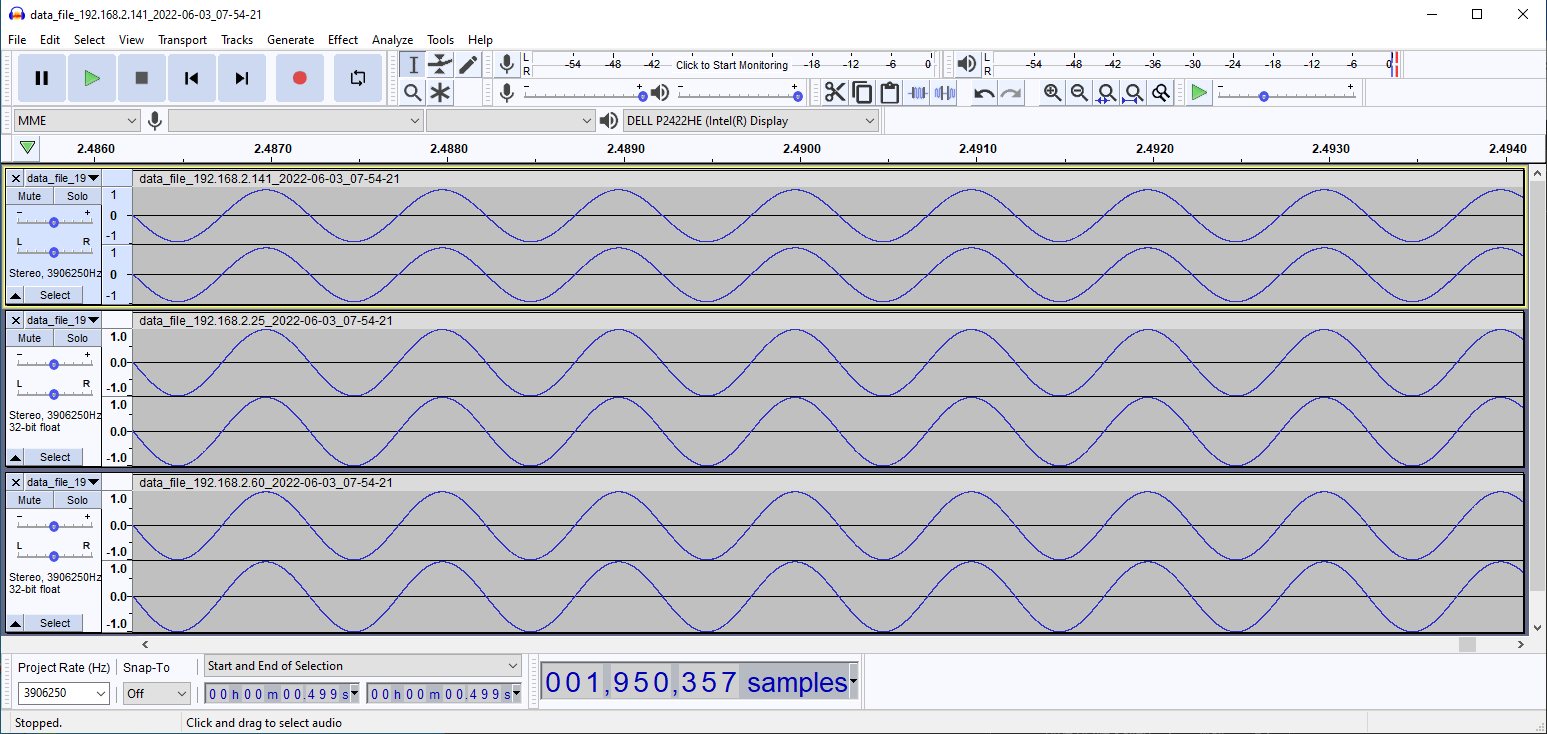
In this example, a 1 kHz sinewave signal was connected to all 6 inputs.
3.4.4. Code examples
Here are examples for synchronising the X-channel system and Click shields through SCPI commands.
3.4.5. Multiboard synchronisation Q&A
Here is a special Q&A section regarding the Red Pitaya Click Shields and their comparison to the X-Channel System. For general Red Pitaya Q&A, please see the FAQ section.
Can I synchronise multiple different Red Pitaya board models with the Click Shields?
Yes, you can. There can be different board models in a Red Pitaya Click Shield daisy chain. For example, the primary device can be a STEMlab 125-14 4-Input board, the first secondary device a STEMlab 125-14 ext. clk., and the second secondary device another 4-Input. This allows for great flexibility in building a multichannel system achieving different combinations of the number of channels. We recommend daisy chaining only devices with the same core clock speed.
Please take into account that SDRlab 122-16 ext. clk. is meant to receive a 122.88 MHz clock signal, so although synchronisation with STEMlab 125-14 boards is possible, we do not recommend it.
While multiple different board models can be daisy chained, some features might be unavailable. See the Click Shield compatibility section.
What is the difference between Red Pitaya X-channel System and Red Pitaya X-channel 2.0 (Click Shield) Synchronisation?
In this section we will talk about the difference between the Red Pitaya X-channel System and Red Pitaya X-channel 2.0 (Click Shield) Synchronisation. It might seem like these two are completely the same, but that is far from the truth.
Note
Please note that the limitations of the Streaming applications are the same for both systems (continuous streaming). More information is available here.
X-Channel System |
X-channel 2.0 (Click Shield) Synchronisation |
|
|---|---|---|
Clock & Sampling rate |
||
Recommended sampling rate |
Up to 100 ksps |
Up to full sampling rate |
Shared clock signal |
Primary device CLK |
Click Shield Oscillator OR external clock |
External clock type |
N/A |
See ZL40213 AC clock input specs |
Clock signal delays |
Slightly higher delay per unit
(signal through each FPGA) [1]
|
Clock buffer (1x per unit) - ZL40213 |
Trigger signal delays |
Slightly higher delay per unit
(signal through each FPGA) [1]
|
|
Pinout |
||
GPIO access |
Full access [2] |
Max 10 digital pins [3] |
Slow analog access |
Full access (4/4) |
Max 2 pins (2/4) [3] |
Digital communication pins |
UART (1x), SPI (1x), I2C (1x), CAN (2x) |
UART (2x), SPI (2x), I2C (2x) (no CAN) [3] |
Units |
||
Compatible Red Pitaya board models |
Primary - STEMlab 125-14 LN
Secondary - STEMlab 125-14 LN Secondary
|
STEMlab 125-14 Pro Gen 2 series
STEMlab 125-14 4-Input
STEMlab TI series
SDRlab 122-16 Ext Clk
STEMlab 125-14 (LN) Ext Clk
|
Choosing between External and Internal clock |
No |
Yes [4] |
Aluminium case compatibility |
No |
Yes |
More information on the hardware is available here:
Red Pitaya Click Shields are used for the X-channel 2.0 synchronisation.
Footnotes