Fast Analog Outputs
This page contains detailed specifications and performance measurements for Original Generation fast analog outputs.
The Red Pitaya board analog front-end features two fast analog outputs.
Specifications
Number of channels |
2 |
Sample rate |
125 Msps |
DAC resolution |
14 bits |
Output coupling |
DC |
Load impedance |
50 Ω |
Full scale power |
> 9 dBm |
Connector type |
SMA |
Output slew rate limit |
200 V/us |
Bandwidth |
50 MHz (3 dB) |
Note
The output channels are designed to drive 50 Ω loads. Terminate outputs when channels are not used. Connect a 50 Ω parallel load (SMA Tee junction) in high-impedance load applications.
Note
The typical power level with 1 MHz sine is 9.5 dBm. Output power is subject to slew rate limitations.
Note
The SMA connectors on the cables connected to Red Pitaya must correspond to the standard MILC39012. The central pin must be of a suitable length, otherwise, the SMA connector, installed on the Red Pitaya, will mechanically damage the SMA connector. The central pin of the SMA connector on the Red Pitaya will lose contact with the board and the board will not be possible to repair due to the mechanical damage (separation of the pad from the board).
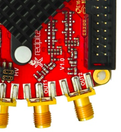
Figure 4.46 Output channel Output voltage range: ±1 V
The output stage is shown in the picture below.
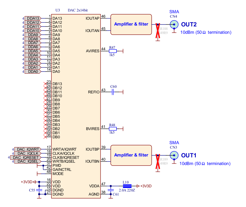
Figure 4.47 Output channel schematics
Output impedance
The impedance of the output channels (output amplifier and filter) is shown in the figure below.
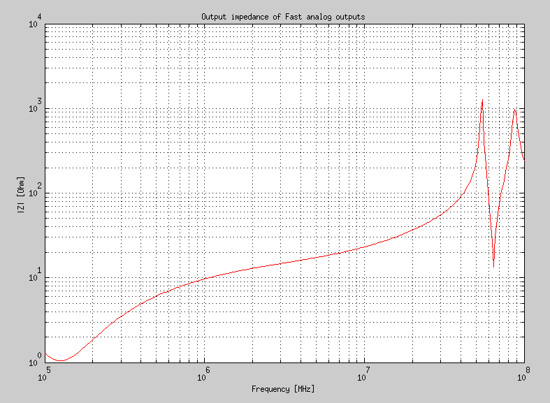
Figure 4.48 Output impedance
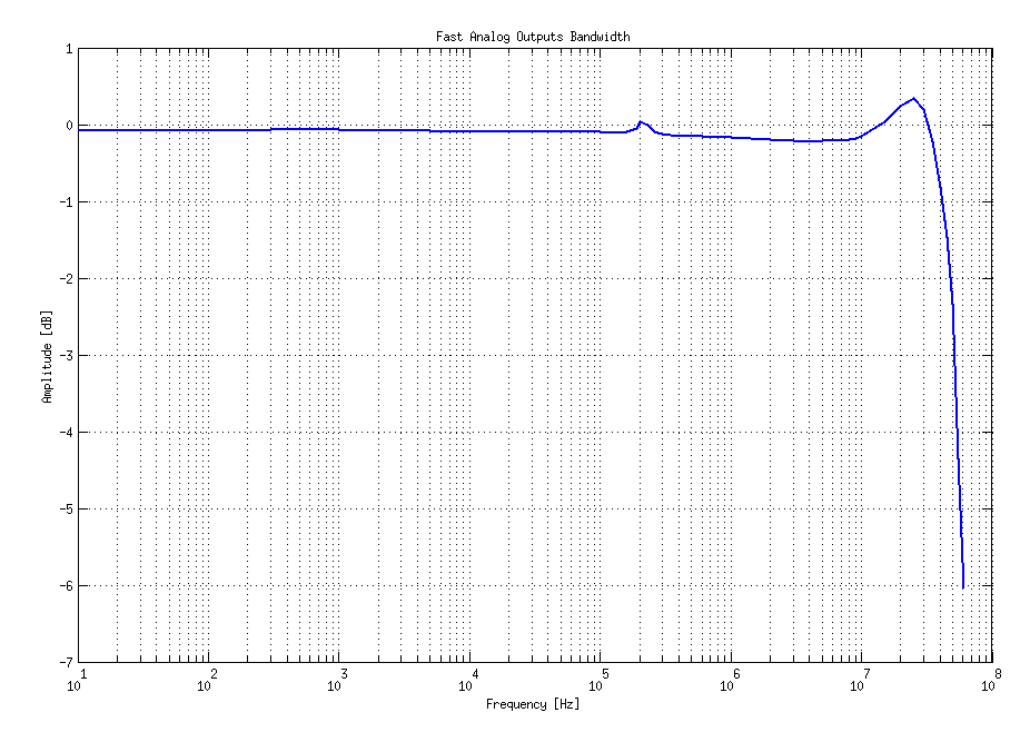
Output bandwidth
Bandwidth |
50 MHz (-3 dB) |
Bandwidth measurements are shown in the picture below. Measurements are taken with the Agilent MSO7104B oscilloscope for each frequency step (10 Hz - 60 MHz) of the measured signal. The Red Pitaya board OUT1 is used with 0 dBm output power. The second output channel and both input channels are terminated with 50 Ohm termination. The Oscilloscope ground is used to ground the Red Pitaya board. The oscilloscope input must be set to 50 Ohm input impedance.
Note that the output phase noise is slightly frequency dependent.
Output harmonics
Typical performance of the output harmonics is shown in the table below.
Output signal frequency (8 dBm) |
Harmonics |
|---|---|
1 MHz |
-51 dBc |
10 MHz |
-49 dBc |
20 MHz |
-48 dBc |
45 MHz |
-53 dBc |
Output DC offset error
DC offset error |
< 5% FS |
Output gain error
Output gain error |
< 5% |
Further corrections can be applied through more precise gain and DC offset calibration.
Analog output calibration
Calibration is performed in a noise-controlled environment. Inputs’ and outputs’ gains are calibrated with 0.02% and 0.003% DC reference voltage standards. Input gain calibration is performed in a medium-sized timebase range. The Red Pitaya is a non-shielded device, and its input/output ground is not connected to the earth’s ground, as is the case in most classical oscilloscopes. To achieve the calibration results given below, Red Pitaya must be grounded and shielded.
Parameter |
Value |
|---|---|
DC GAIN ACCURACY |
0.4% |
DC OFFSET |
±4 mV |
RIPPLE(@ 0.5V DC) |
0.4 mVpp |
Typical specifications after calibration