CAN Loopback
Description
This example demonstrates communication using the Red Pitaya CAN interface. The code below simulates a loopback by sending a message from the CAN socket.
Required hardware
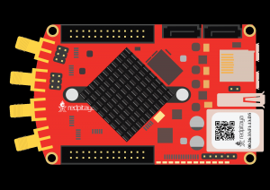
Red Pitaya
Require software
2.04-35 or higher OS
Note
This code is written for 2.04-35 or higher OS. For older OS versions, please check when specific commands were released (a note is added to each command introduced in 2.00 or higher verisons).
Connections
Although the CAN transceiver is not required for this example because the loopback mode connects the TX and RX pins on the FPGA level, the connection instructions are still included.
Connecting the MCP2452 Click Board (or another CAN transciever) to the Red Pitaya:
TX pins of the CAN transceivers to the CAN RX pins on the Red Pitaya
RX pins of the CAN transceivers to the CAN TX pins on the Red Pitaya
Connect the power and ground pins
Use a DB-9 (or a different) cable to connect the CAN transceiver to an external CAN bus or to another MPC2542 click board
Note
CAN0 - TX == DIO7_N, RX == DIO7_P
CAN1 - TX == DIO6_N, RX == DIO6_P

Here is the CAN pinout for the DB-9 connector:

Figure 3.12 Image source: CSS Electronics
SCPI Code Examples
Note
This code is written for 2.04-35 or higher OS. For older OS versions, please check when specific commands were released (a note is added to each command introduced in 2.00 or higher verisons).
Code - MATLAB®
The code is written in MATLAB. TCP client communication is used to establish socket communication with Red Pitaya, then SCPI commands are sent to configure the various Red Pitaya peripherals. Copy the code below into the MATLAB editor, save the project and press the Run button. Tested on MATLAB 2024b.
%% Define Red Pitaya as TCP/IP object
clc
close all
IP = 'rp-f0a235.local';           % IP of your Red Pitaya
port = 5000;
RP = tcpclient(IP, port);

% Variables
bitrate = 200000;
can_id = 123;
timeout_rx = 2000;
can_mode = 'LOOPBACK';
can_data = [1 2 3];

%% Open connection with your Red Pitaya
RP.ByteOrder = 'big-endian';
configureTerminator(RP,'CR/LF');
flush(RP);
fprintf('Start\n');

% INIT CAN %
writeline(RP, 'CAN:FPGA ON');

% CAN 0 SETUP %
writeline(RP, 'CAN0:STOP');
writeline(RP, append('CAN0:BITRate ', num2str(bitrate)));
writeline(RP, append('CAN0:MODE ', can_mode,',ON'));

% Start and open the CAN0 interface %
writeline(RP, 'CAN0:START');
writeline(RP, 'CAN0:OPEN');

% Send and read data %
writeline(RP, append('CAN0:Send', num2str(can_id), ' ', strjoin(compose('%d',can_data),',')));

rx_data = writeread(RP, append('CAN0:Read:Timeout', num2str(timeout_rx), '?'))

% Close the interface %
writeline(RP, 'CAN0:CLOSE');
fprintf('End program\n');
clear RP;
Code - Python
Using SCPI commands:
#!/usr/bin/python3

import numpy as np
import redpitaya_scpi as scpi

IP = 'rp-f0a235.local'

can_bus = 0
bitrate = 200000
can_id = 123
timeout_rx = 2000
can_mode = "loopback"

tx_buffer = np.arange(3)
print(f"Data: {np.array2string(tx_buffer, separator=',').replace('[','').replace(']','')}")

rp = scpi.scpi(IP)

# INIT CAN #
rp.tx_txt('CAN:FPGA ON')
print("CAN:FPGA ON")
rp.check_error()

## CAN 0 SETUP ##
# GPIO (N7,P7)
rp.tx_txt(f'CAN{can_bus}:STOP')
rp.check_error()

rp.tx_txt(f'CAN{can_bus}:BITRate {bitrate}')
rp.check_error()

rp.tx_txt(f'CAN{can_bus}:MODE {can_mode.upper()},ON')
rp.check_error()

# Start and open the CAN0 interface
rp.tx_txt(f'CAN{can_bus}:START')
rp.check_error()

rp.tx_txt(f'CAN{can_bus}:OPEN')
rp.check_error()

# Send and read data
rp.tx_txt(f'CAN{can_bus}:Send{can_id} {np.array2string(tx_buffer, separator=',').replace('[','').replace(']','')}')
rp.check_error()

rp.tx_txt(f'CAN{can_bus}:Read:Timeout{timeout_rx}?')
print(f"Read data: {rp.rx_txt()}")

# Close the interface
rp.tx_txt(f'CAN{can_bus}:CLOSE')
rp.check_error()
rp.close()
Note
The Python functions are accessible with the latest version of the redpitaya_scpi.py document available on our GitHub. The functions represent a quality-of-life improvement as they combine the SCPI commands in an optimal order and also check for improper user inputs. The code should function at approximately the same speed without them.
For further information on functions please consult the redpitaya_scpi.py code.
API Code Examples
Note
The API code examples don’t require the use of the SCPI server. Instead, the code should be compiled and executed on the Red Pitaya itself (inside Linux OS). Instructions on how to compile the code and other useful information are here.
Code - C++
Note
The API code examples don’t require the use of the SCPI server. Instead, the code should be compiled and executed on the Red Pitaya itself (inside Linux OS). Instructions on how to compile the code and other useful information are here.
/* @brief This is a simple application for testing CAN communication on a Red Pitaya
*
* (c) Red Pitaya  http://www.redpitaya.com
*
* This part of code is written in C++ programming language.
* Please visit https://en.wikipedia.org/wiki/C%2B%2B
* for more details on the language used herein.
*/

#include <stdio.h>
#include <stdlib.h>
#include <string.h>
#include "rp_hw_can.h"

int main(int argc, char *argv[]){

    int res;
    int bitrate = 200000;

    int can_id = 123;

    int timeout_rx = 2000;

    unsigned char tx_buffer[8];
    memset(tx_buffer, '0', 8);

    tx_buffer[0] = '1';
    tx_buffer[1] = '2';
    tx_buffer[2] = '3';
    tx_buffer[3] = '4';
    tx_buffer[4] = '5';

    printf("Tx buffer data: %s\n", tx_buffer);

    /* INIT CAN */
    res = rp_CanSetFPGAEnable(true);
    printf("Init result: %d\n",res);

    /* CAN 0 SETUP */
    // GPIO (N7,P7)
    res = rp_CanStop(RP_CAN_0);                 // set can0 interface to DOWN for configuration
    printf("Stop can0: %d\n",res);

    res = rp_CanSetBitrate(RP_CAN_0, bitrate);    // set can0 bitrate
    printf("Set bitrate: %d\n",res);

    res = rp_CanSetControllerMode(RP_CAN_0,RP_CAN_MODE_LOOPBACK,true);  // set loopback mode
    printf("Set loopback mode ON: %d\n",res);

    /* Start and open the CAN0 interface*/
    res = rp_CanStart(RP_CAN_0);            // set can0 interface to UP
    printf("Start can0: %d\n",res);

    res = rp_CanOpen(RP_CAN_0);             // open socket for can0
    printf("Open socket: %d\n",res);

    /* Send and read data */
    res = rp_CanSend(RP_CAN_0, can_id, tx_buffer, 3, false, false, 0);  // write buffer to can0
    printf("Write result: %d\n",res);

    rp_can_frame_t frame;
    res = rp_CanRead(RP_CAN_0, timeout_rx, &frame);     // read frame from can0
    printf("Read result: %d\n",res);
    printf("Can ID: %d data: %d,%d,%d\n",frame.can_id,frame.data[0],frame.data[1],frame.data[2]);

    /* Close the interface */
    res = rp_CanClose(RP_CAN_0);            // close socket for can0
    printf("Close can0 result: %d\n",res);
    return 0;
}
Code - Python API
#!/usr/bin/env python3

""" Python API example of CAN communication """

import numpy as np
import rp
import rp_hw_can

# Variables

can = rp_hw_can.RP_CAN_0                    # RP_CAN_0 == DIO7_P, DIO7_N ### RP_CAN_1 == DIO6_P, DIO6_N
can_id = 123
can_bitrate = 200000                        # 1 - 10000000
can_mode = rp_hw_can.RP_CAN_MODE_LOOPBACK   # RP_CAN_MODE_LOOPBACK, RP_CAN_MODE_LISTENONLY,
                                            # RP_CAN_MODE_3_SAMPLES, RP_CAN_MODE_ONE_SHOT,
                                            # RP_CAN_MODE_BERR_REPORTING

can_extended_frame = False                  # Extended can frame (True/False)
can_rtr = False                             # Remote request frame (True/False)
can_tx_timeout = 0                          # Timeout in milliseconds (0 == disabled)
can_rx_timeout = 0

tx_buffer = np.arange(8, dtype=np.uint8)
rx_buffer = np.zeros(8, dtype=np.uint8)

print(f"TX data: {tx_buffer}")
print(f"RX data: {rx_buffer}")

rp.rp_Init()

### Init CAN ###

rp_hw_can.rp_CanSetFPGAEnable(True)                     # Init CAN in FPGA - pass the data from CAN controller to GPIO

### CAN 0 Setup ###
rp_hw_can.rp_CanStop(can)                               # Set CAN state to DOWN for configuration

rp_hw_can.rp_CanSetBitrate(can, can_bitrate)            # Set bitrate
rp_hw_can.rp_CanSetControllerMode(can, can_mode, True)  # Set controller mode

### Start and open the CAN0 interface ###
rp_hw_can.rp_CanStart(can)                              # Start CAN interface (line to UP)
rp_hw_can.rp_CanOpen(can)                               # Open socket for CAN
print("CAN ready")
### Send and receive data ###

# Write buffer to CAN
print(rp_hw_can.rp_CanSendNP(can, can_id, can_extended_frame, can_rtr, can_tx_timeout, tx_buffer))
print(f"Data sent: {tx_buffer}")

# Read frame from CAN
print(rp_hw_can.rp_CanReadNP(can, can_rx_timeout, rx_buffer))
print(f"Data received: {rx_buffer}")

### Close socket ###
rp_hw_can.rp_CanClose(can)

# Release resources
print("Program END")
rp.rp_Release()