Programming Red Pitaya via JTAG
JTAG (Joint Test Action Group) programming allows direct FPGA configuration from Xilinx Vivado, bypassing the need for SSH file transfer and command-line tools. This method is particularly useful for rapid prototyping, debugging, and development workflows.
Overview
When to Use JTAG Programming
JTAG programming is ideal for:
Development and Debugging:
Rapid prototyping with instant FPGA updates
Debugging FPGA designs with integrated logic analyzers (ILA)
Testing bitstreams before deploying to production
Iterative development without SSH overhead
Recovery Scenarios:
Recovering from corrupted SD card or boot failure
Testing FPGA without functional Linux system
Direct hardware access when network is unavailable
Bypassing software layer for pure FPGA testing
Production and Testing:
Manufacturing test and quality control
Batch programming of multiple boards
Automated testing with Vivado TCL scripts
Initial board bring-up and validation
Advantages vs. SSH Upload
JTAG Programming:
Direct from Vivado IDE (one-click programming)
Integrated with debugging tools (ILA, VIO)
Faster for iterative development
Works without functional OS
Real-time signal monitoring with Vivado
SSH Upload:
No special hardware required
Can be automated with scripts
Works remotely over network
Includes device tree loading
Persists after programming
Important
JTAG programming is volatile - the FPGA configuration is lost when:
Red Pitaya is powered off
FPGA is reprogrammed via SSH
System reboots
For persistent configuration, use SSH upload with boot loading.
Hardware Requirements
JTAG Cable Selection
Red Pitaya requires a JTAG cable compatible with Xilinx Zynq-7000 devices. The following cables are tested and supported:
Recommended Cables
Cable Model |
Connection |
Notes |
|---|---|---|
Digilent JTAG-HS3 |
14-pin connector + 14-to-6-pin adapter required |
High-speed, most commonly used |
Digilent JTAG-HS2 |
6-pin connector (direct connection) |
More convenient (no adapter needed) |
Xilinx Platform Cable USB II |
14-pin connector + adapter |
Official Xilinx cable |
Other Compatible Cables
Any Xilinx-compatible JTAG cable should work. For a complete list, see:
Xilinx UG908 - Programming and Debugging (Appendix D)
Required Adapters
If using JTAG-HS3 or similar 14-pin cable:
14-pin to 6-pin adapter - Converts standard 14-pin JTAG to Red Pitaya’s 6-pin header
Available from Digilent or third-party suppliers
Ensure correct pin mapping (see pinout section below)
Physical Connection
JTAG Connector Location
The JTAG connector is a 6-pin header located on Red Pitaya’s PCB:
Top side: No marking
Bottom side: Pins are clearly marked with labels
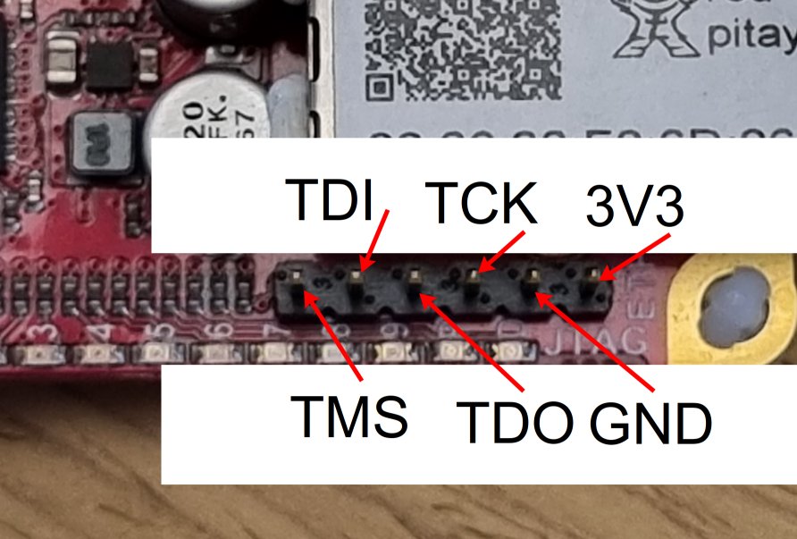
Figure 4.56 JTAG connector pin markings on Red Pitaya PCB bottom side
JTAG Pinout
Red Pitaya’s 6-pin JTAG header follows standard ARM JTAG pinout:
Pin 1: VCC  (3.3V)    Pin 2: GND
Pin 3: TDI            Pin 4: TMS
Pin 5: TCK            Pin 6: TDO
Pin 1 orientation: Look for the square pad or the marking on the PCB bottom.
Connection Procedure
Ensure Red Pitaya is powered off
Orient the cable correctly - Pin 1 (VCC) should match the square pad
Insert cable firmly - Ensure all 6 pins make contact
Connect USB to computer
Power on Red Pitaya
Warning
Incorrect polarity can damage the JTAG interface!
Always double-check pin 1 orientation before connecting
If in doubt, compare with PCB markings
Some cables have a keying notch - don’t force it
Software Installation
Prerequisites
Before starting, ensure you have:
Xilinx Vivado (2020.1 or newer) installed
USB port available on your computer
Administrator/sudo privileges for driver installation
See also
Need to install Vivado? See Vivado Installation Guide
Step 1: Install Digilent Adept 2
Digilent Adept provides drivers and utilities for Digilent JTAG cables.
Download Adept 2
Visit: https://digilent.com/reference/software/adept/start
Download both packages:
Adept 2 Runtime - Core drivers
Adept 2 Utilities - Configuration tools
Linux Installation
Download .deb packages for Ubuntu/Debian:
# Install Runtime
sudo dpkg -i digilent.adept.runtime_<version>_amd64.deb

# Install Utilities
sudo dpkg -i digilent.adept.utilities_<version>_amd64.deb

# If dependency errors occur, fix them
sudo apt-get install -f
Verify installation:
# Check if Adept utilities are available
djtgcfg --version
Windows Installation
Run installers:
Double-click
AdeptRuntime_<version>.msiFollow installation wizard
Restart if prompted
Double-click
AdeptUtilities_<version>.msiFollow installation wizard
Verify installation:
Open Command Prompt and run:
djtgcfg enum
Step 2: Verify JTAG Cable Detection
Linux Verification
Check USB device:
lsusb | grep -i ftdi
Expected output for JTAG-HS3:
Bus 001 Device 005: ID 0403:6014 Future Technology Devices International, Ltd FT232H Single HS USB-UART/FIFO IC
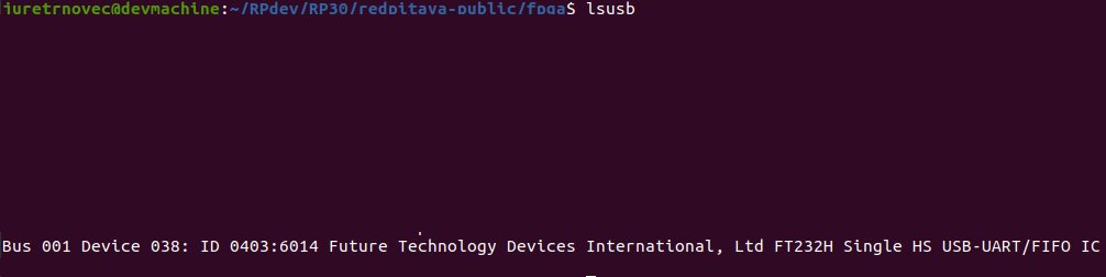
Figure 4.57 JTAG-HS3 appears as FTDI device in lsusb output
Check Digilent driver detection:
djtgcfg enum
Expected output:
Found 1 device(s)

Device: JtagHs3
    Product Name:   Digilent JTAG-HS3
    User Name:      JtagHs3
    Serial Number:  210299123456
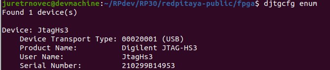
Figure 4.58 Digilent driver successfully detects JTAG cable
Windows Verification
Check Device Manager:
Open Device Manager (devmgmt.msc)
Look under “Universal Serial Bus controllers”
Find “Digilent USB Device” or similar
Check with Adept:
Open Command Prompt:
djtgcfg enum
Should list connected Digilent devices.
Troubleshooting Detection Issues
Cable Not Detected
Linux:
# Check if device appears in kernel messages
dmesg | grep -i ftdi
dmesg | grep -i usb

# Check USB permissions
ls -l /dev/bus/usb/*/*

# Add user to dialout group for USB access
sudo usermod -aG dialout $USER
# Log out and log back in
Windows:
Check Device Manager for yellow exclamation marks
Reinstall Adept 2 Runtime
Try different USB port
Check USB cable quality
Driver Issues
Linux - Missing libraries:
# Install required libraries
sudo apt-get install libusb-1.0-0 libftdi1
Windows - Driver conflicts:
Uninstall conflicting FTDI drivers
Use Zadig tool to reinstall WinUSB driver
Reboot after driver changes
Vivado Configuration
Step 1: Open Hardware Manager
From Vivado IDE:
Click Flow Navigator → Program and Debug → Open Hardware Manager
Or from menu: Tools → Open Hardware Manager
Hardware Manager window opens
Step 2: Auto Connect to Cable
In Hardware Manager:
Click Open Target → Auto Connect
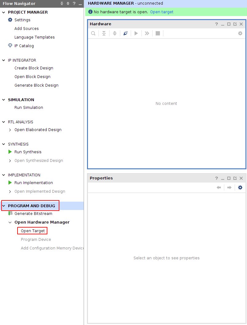
Figure 4.59 Opening Hardware Manager and auto-connecting to JTAG cable
Vivado searches for JTAG cables
If successful, cable appears under localhost in Hardware window
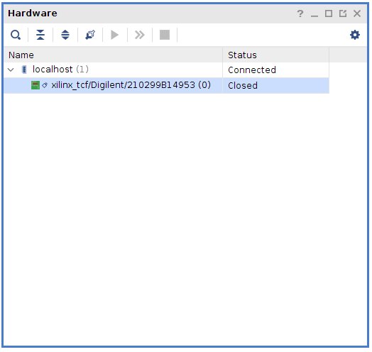
Figure 4.60 JTAG cable detected and listed under localhost
Step 3: Connect Red Pitaya
Ensure Red Pitaya is powered on
Connect JTAG cable to Red Pitaya’s 6-pin header
In Vivado, click refresh if device doesn’t appear automatically
Zynq device appears in Hardware window:
STEMlab 125-10/14:
xc7z010_1(Zynq-7010)STEMlab 125-14 Z7020, SDRlab, SIGNALlab:
xc7z020_1(Zynq-7020)
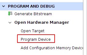
Figure 4.61 Zynq device (xc7z010) detected via JTAG
Manual Connection (Alternative)
If auto-connect fails:
Click Open Target → Open New Target
Follow wizard:
Select Local server
Select detected hardware server
Choose your JTAG cable
Click Finish
Programming Procedure
Step 1: Select Device
In Hardware window:
Right-click on the Zynq device (e.g.,
xc7z010_1)Select Program Device…
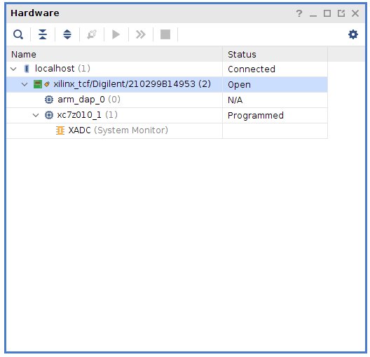
Figure 4.62 Right-click menu showing “Program Device” option
Step 2: Select Bitstream File
Program Device dialog appears:
Bitstream file field:
Click Browse button (📁)
Navigate to your
.bitfile locationSelect the bitstream:
red_pitaya_top.bit
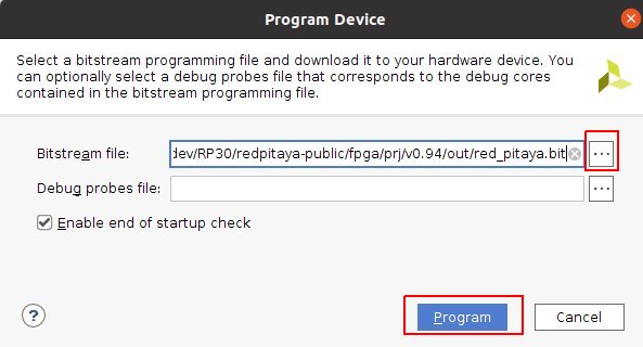
Figure 4.63 Bitstream file selection dialog
Debug probes file (optional):
Leave blank unless using Integrated Logic Analyzer (ILA)
If using ILA, select corresponding
.ltxfile
Note
Bitstream location after build:
fpga/prj/<project_name>/out/red_pitaya_top.bit
Or within Vivado project:
fpga/prj/<project_name>/project/redpitaya.runs/impl_1/red_pitaya_top.bit
Step 3: Program FPGA
Click Program button
Progress window shows programming status:
Programming device...
Loading configuration data...
Bitstream loaded successfully
Configuration complete
Success message appears in TCL console:
INFO: [Labtools 27-3164] End of startup status: HIGH
INFO: [Labtoolstcl 44-377] Flash programming completed successfully
FPGA is now configured - Red Pitaya begins operating with new FPGA design
Step 4: Verify Programming
Visual verification:
Check LED patterns on Red Pitaya (should match your design)
Observe expected behavior
Register verification:
If Red Pitaya Linux is running, check via SSH:
# Read a known register to verify FPGA is responding
ssh root@rp-xxxxxx.local
redpitaya> /opt/redpitaya/bin/monitor 0x40000000
Vivado verification:
In Hardware window, device status should show:
DONE: True
Status: Configuration successful
Advanced Usage
Programming via TCL Script
Automate JTAG programming using Vivado TCL commands:
Create script: program_jtag.tcl
# Open hardware manager
open_hw_manager

# Connect to local hardware server
connect_hw_server -url localhost:3121

# Open target
current_hw_target [get_hw_targets */xilinx_tcf/Digilent/*]
set_property PARAM.FREQUENCY 15000000 [get_hw_targets */xilinx_tcf/Digilent/*]
open_hw_target

# Set bitstream file
current_hw_device [get_hw_devices xc7z010_1]
set_property PROGRAM.FILE {/path/to/red_pitaya_top.bit} [get_hw_devices xc7z010_1]

# Program device
program_hw_devices [get_hw_devices xc7z010_1]

# Verify
refresh_hw_device [get_hw_devices xc7z010_1]

# Close connections
close_hw_target
close_hw_manager
Run script:
vivado -mode batch -source program_jtag.tcl
Adjusting JTAG Clock Frequency
Default JTAG clock is 10 MHz. Adjust for stability or speed:
In Vivado GUI:
Right-click JTAG cable in Hardware window
Select Properties
Change Frequency parameter
Click OK
Recommended frequencies:
Stable connections: 10 MHz (default)
Long cables or noise: 5 MHz or lower
Short cables, high speed: 15-20 MHz
Via TCL:
set_property PARAM.FREQUENCY 10000000 [get_hw_targets */xilinx_tcf/Digilent/*]
Using Integrated Logic Analyzer (ILA)
Debug internal FPGA signals with Vivado’s ILA:
Prerequisites:
ILA IP core added to FPGA design
.ltxdebug probes file generated during synthesis
Programming with ILA:
In Program Device dialog, browse for
.ltxfileProgram device
ILA cores appear in Hardware window
Configure trigger conditions
Run ILA to capture waveforms
ILA file location:
fpga/prj/<project_name>/project/redpitaya.runs/impl_1/red_pitaya_top.ltx
See Xilinx UG908 Chapter 8 for complete ILA usage.
Batch Programming Multiple Boards
For production or testing multiple Red Pitayas:
Setup:
Use USB hub to connect multiple JTAG cables
Assign unique serial numbers to each cable
Create TCL script for each board
Script template:
# Target specific cable by serial number
current_hw_target [get_hw_targets */xilinx_tcf/Digilent/210299123456]
open_hw_target

# Program
current_hw_device [get_hw_devices xc7z010_1]
set_property PROGRAM.FILE {red_pitaya_top.bit} [get_hw_devices xc7z010_1]
program_hw_devices [get_hw_devices xc7z010_1]

close_hw_target
Remote JTAG Programming
Program Red Pitaya over network using Vivado Hardware Server:
On Remote Machine (where Red Pitaya is connected):
# Start hardware server
hw_server
On Local Machine (running Vivado):
In Hardware Manager, click Open New Target
Select Remote server
Enter remote machine’s IP address and port (default: 3121)
Continue with normal programming procedure
Troubleshooting
Cable Not Detected in Vivado
Problem: JTAG cable doesn’t appear in Hardware Manager
Solutions:
Verify USB connection:
lsusb | grep -i ftdi  # Linux
# Or check Device Manager (Windows)
Check Digilent drivers:
djtgcfg enumIf cable not listed, reinstall Adept 2
Restart Hardware Server:
# Linux
killall hw_server
hw_server &
In Vivado, reconnect to server
Check Vivado cable drivers:
cd $XILINX_VIVADO/data/xicom/cable_drivers/lin64/install_script/install_drivers
sudo ./install_drivers
Device Not Appearing After Cable Connection
Problem: JTAG cable detected, but Zynq device doesn’t appear
Check:
Red Pitaya is powered on:
LEDs should be lit
Power supply connected
Check power LED
JTAG cable properly connected:
Pins aligned correctly
Pin 1 (VCC) matches square pad
All 6 pins making contact
Cable firmly seated
Refresh in Vivado:
Right-click cable in Hardware window
Select Refresh Device
Check JTAG chain:
In TCL console:
get_hw_devicesShould return
xc7z010_1orxc7z020_1
Programming Fails with Error
Problem: Programming starts but fails with error
Common errors and solutions:
“DONE pin did not go high”
FPGA failed to configure properly
Check bitstream is correct for board model (Z10 vs Z20)
Verify bitstream file is not corrupted
Try regenerating bitstream in Vivado
“Failed to program device”
Check JTAG connection quality
Lower JTAG clock frequency
Check for poor solder joints on JTAG header
Try different JTAG cable
“Device not in chain”
JTAG connection lost during programming
Check cable connection
Ensure stable power supply
Check for USB hub issues (try direct connection)
FPGA Programs But Doesn’t Work
Problem: Programming succeeds but Red Pitaya doesn’t behave as expected
Debug steps:
Verify correct bitstream:
Check board model in Vivado project matches hardware
Z10 boards need Z10 bitstream
Z20 boards need Z20 bitstream
Check if Linux interferes:
JTAG programming doesn’t load device tree, which may cause conflicts:
# Stop Red Pitaya services that access FPGA
ssh root@rp-xxxxxx.local
redpitaya> systemctl stop redpitaya_*
Test with simple design:
Program with known-good bitstream (e.g., factory v0.94)
If that works, issue is with custom design
If that fails, hardware or connection issue
Check clock configuration:
Ensure PS (ARM) clocks are configured
Verify PL clock is enabled in FPGA design
Check clock frequencies match constraints
Use ILA to debug:
Add ILA cores to monitor internal signals
Check if expected signals are toggling
Verify AXI bus transactions
Linux XADC/GPIO Access After JTAG Programming
Problem: After JTAG programming, Linux drivers can’t access FPGA peripherals
Cause: Device tree not loaded (JTAG only programs FPGA, not device tree)
Solution:
Option 1 - Reload device tree manually:
# Load device tree overlay for your project
ssh root@rp-xxxxxx.local
redpitaya> overlay.sh v0.94
Option 2 - Use SSH programming instead:
For production use, SSH upload with overlay.sh loads both FPGA and device tree.
Permission Denied Errors (Linux)
Problem: USB access denied or permission errors
Solution:
# Add user to dialout group
sudo usermod -aG dialout $USER

# Add udev rules for FTDI devices
echo 'SUBSYSTEM=="usb", ATTRS{idVendor}=="0403", MODE="0666"' | \
    sudo tee /etc/udev/rules.d/52-ftdi.rules

# Reload udev rules
sudo udevadm control --reload-rules
sudo udevadm trigger

# Log out and log back in for group changes to take effect
Best Practices
Development Workflow
Recommended workflow for efficient FPGA development:
Initial setup:
Connect JTAG cable once
Keep connection throughout development session
Leave Hardware Manager open
Design iteration:
Make changes in Vivado
Run synthesis and implementation
Program via JTAG (one click)
Test on hardware
Repeat
Final deployment:
Once design is stable, switch to SSH upload
Configure boot loading if needed
Test complete boot sequence
Cable Management
Keep JTAG cable connected during active development
Use cable ties to prevent strain on connector
Avoid bending cable near connectors
Store cable properly when not in use
Label cables if using multiple boards
Safety Considerations
Always power off before connecting/disconnecting JTAG
Double-check pin orientation before connecting
Use proper ESD precautions when handling cables
Keep JTAG connector clean and free of debris
Don’t force connections - pins should align naturally
Version Control
When using JTAG for development:
Commit bitstream files to version control
Tag working versions for easy rollback
Document programming date/time in log
Keep notes on what works vs. what doesn’t
Production Considerations
For manufacturing or batch programming:
Test JTAG setup thoroughly before production run
Create automated TCL scripts for consistency
Implement verification step after programming
Log programming results for traceability
Have backup cables available