Fast Analog Outputs
This page contains detailed specifications and performance measurements for Gen 2 fast analog outputs.
Specifications
Parameter |
Value |
Units |
Notes |
|---|---|---|---|
|
|||
RF output channels |
2 |
- |
|
Sampling rate |
125 |
MS/s |
|
DAC resolution |
14 |
bit |
|
Load impedance |
50 Ω (Hi-Z) |
- |
|
Voltage range |
±1 @ 50 Ω
±2 @ Hi-Z
|
V |
|
Output coupling |
DC |
- |
|
Short circuit protection |
Yes |
- |
|
Output slew rate |
200 |
V/μs |
|
RF output jitter @40 MHz |
20 |
ps |
RMS, typical |
Bandwidth |
DC - 50 |
MHz |
Typical |
Connector type |
SMA |
- |
|
Note
The output load impedance should be set in the software before connecting the load.
Hardware Details
Output stage schematics
The output stage consists of a buffer amplifier, low-pass filter filter, and DAC driver.
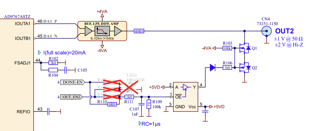
For more information, please refer to each board’s hardware documentation.
Performance Measurements
Output bandwidth
Load impedance |
Bandwidth |
|---|---|
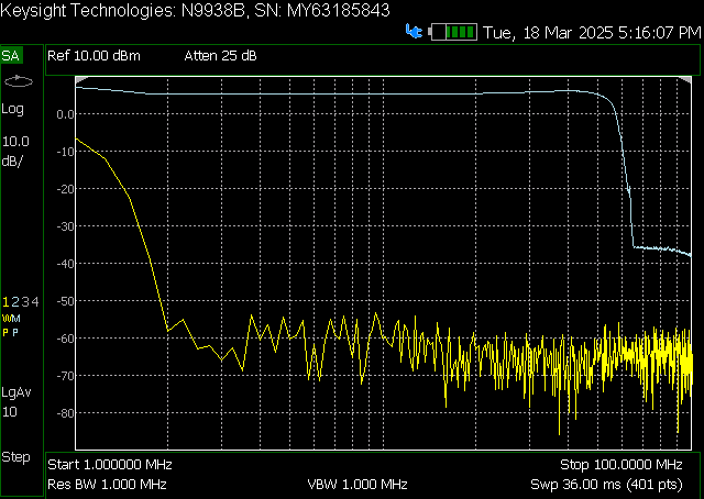
50 Ω |
54.3 MHz (-3 dB) |
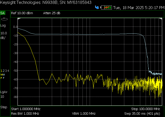
High-Z |
55.0 MHz (-3 dB) |
Bandwidth measurement of the output channel 1 at 50 Ω load.
Bandwidth measurement of the output channel 1 at high impedance load.
Output bandwidth flatness
The output bandwidth flattness is within -1 dB from DC to full (-3 dB) bandwidth.
Output impedance
The impedance of the output channels (output amplifier and filter) is shown in the figure below. The original STEMlab 125-14 output impedance is shown for comparison.
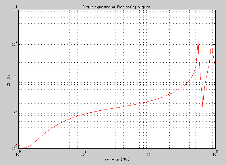
Original board and Gen 2 output impedance measurement.
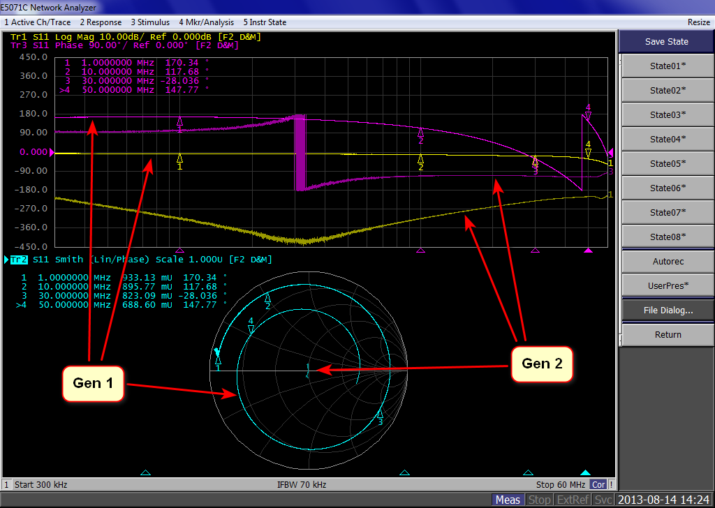
Smith diagram of the output impedance of original board and Gen 2.
Output phase noise
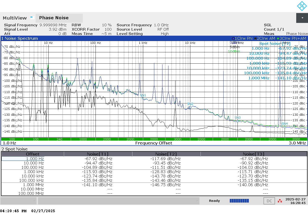
Phase noise measurements between 1 Hz and 1 MHz.
Output SFDR
OUT 1 |
OUT 2 |
|
|---|---|---|
f [MHz] |
SFDR [dB] |
SFDR [dB] |
0.1 |
56 |
54 |
1 |
52 |
58 |
10 |
58 |
55 |
20 |
44 |
44 |
30 |
45 |
45 |
40 |
44 |
45 |
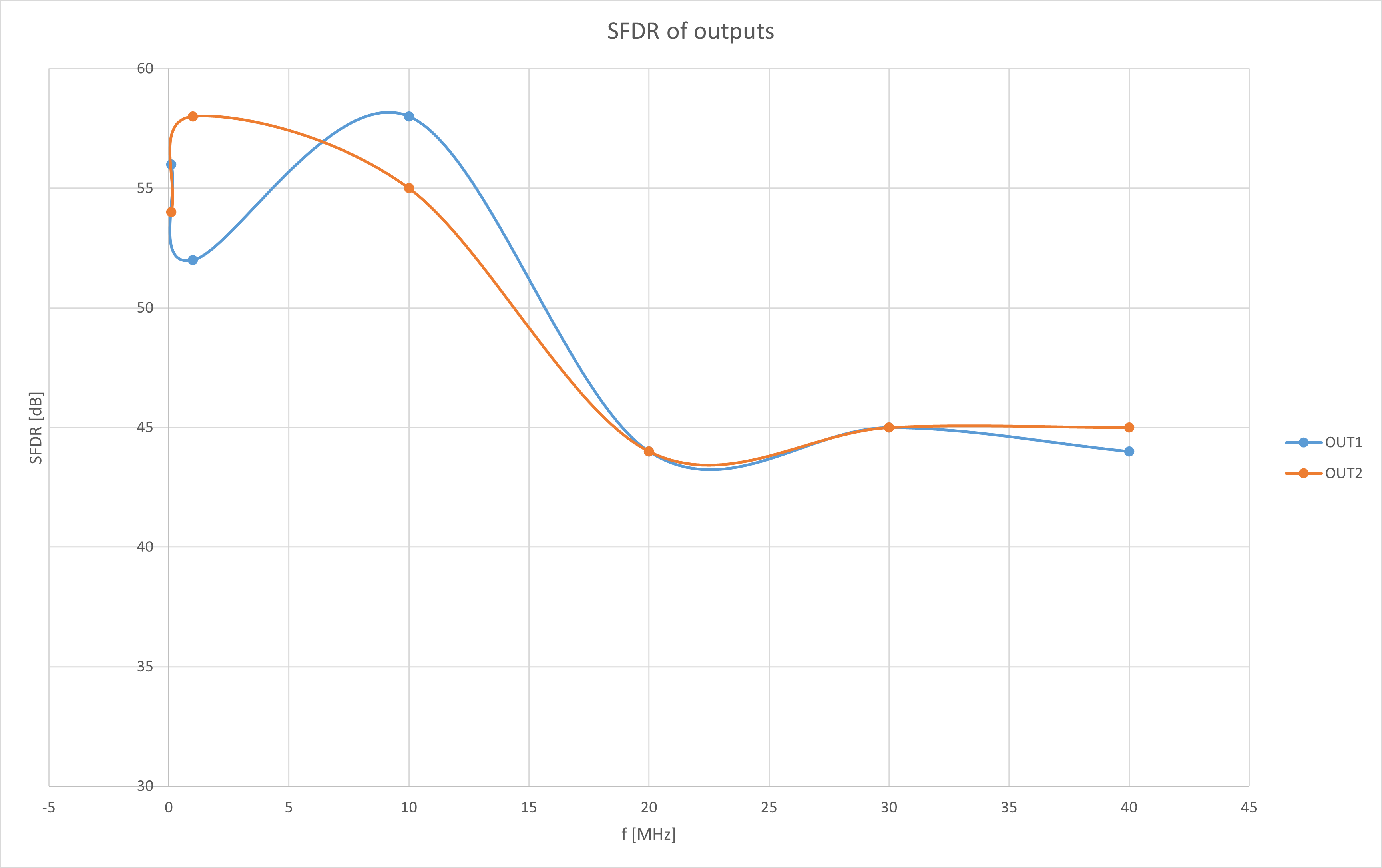
SFDR measurement for both output channels.
Measurements at specific frequencies
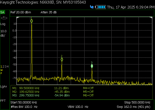
SFDR at 100 kHz.
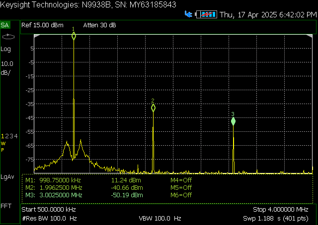
SFDR at 1 MHz.
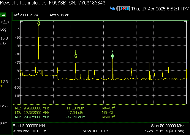
SFDR at 10 MHz.
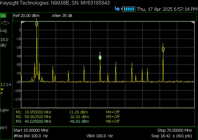
SFDR at 20 MHz.
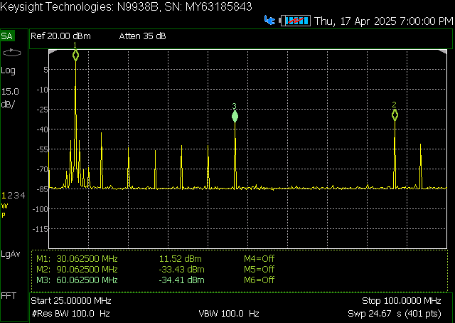
SFDR at 30 MHz.
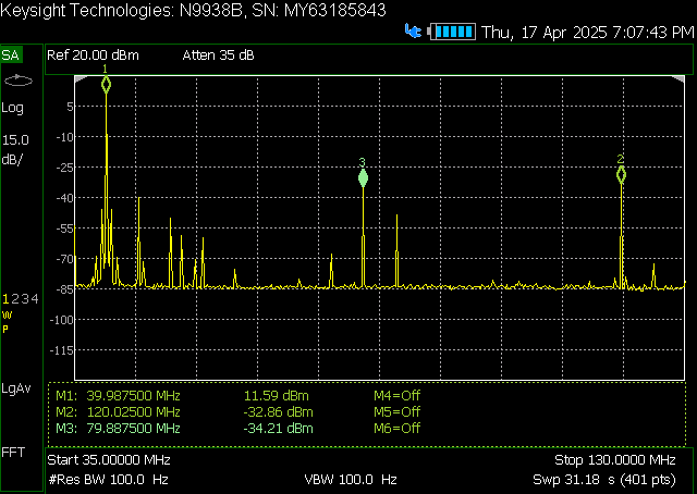
SFDR at 40 MHz.
Output SNR
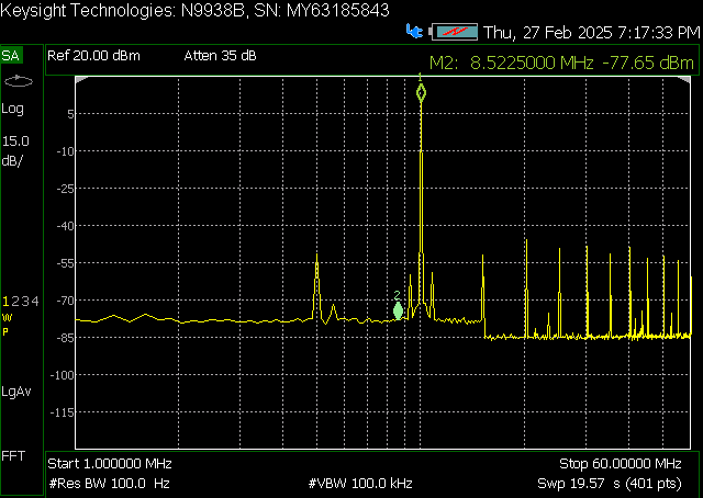
SNR measurement of the output channel 1 (whole specturm).
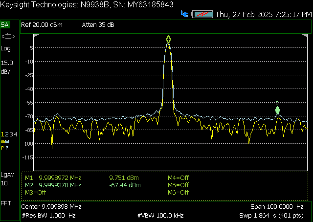
SNR measurement of the output channel 1 (VBW 100 kHz).
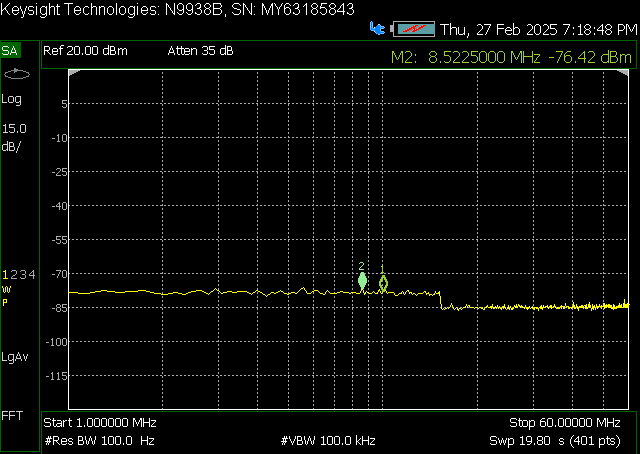
SNR measurement of the output channel 1 (no signal).
Calibration
Analog output calibration
To calibrate the analog outputs, please refer to the Calibration guide.