Fast Analog Inputs
This page contains detailed specifications and performance measurements for Gen 2 fast analog inputs.
Specifications
Parameter |
Value |
Units |
Notes |
|---|---|---|---|
|
|||
RF input channels |
2 |
- |
|
Sampling rate |
125 |
MS/s |
|
ADC resolution |
14 |
bit |
|
Input impedance |
1 MΩ (10 pF) |
- |
|
Full scale voltage range |
±1 (LV)
±20 (HV)
|
V |
|
Input coupling |
DC |
- |
|
Absolute max. input voltage |
±6 (LV)
±30 (HV)
|
V |
DC values [1] |
Input ESD protection |
Yes |
- |
|
Overload protection |
Protection diodes |
- |
(within input voltage ratings) |
Bandwidth |
DC - 50 |
MHz |
Typical |
Connector type |
SMA |
- |
|
Note
Overload protection applies to low frequency signals. For input signals containing frequency components above 1 kHz, where capacitor divider comes into play, the full scale value defines the maximum permissible input voltage.
Hardware Details
Input stage schematics
The input stage consists of a voltage divider, buffer amplifier, anti-aliasing filter, and ADC driver.
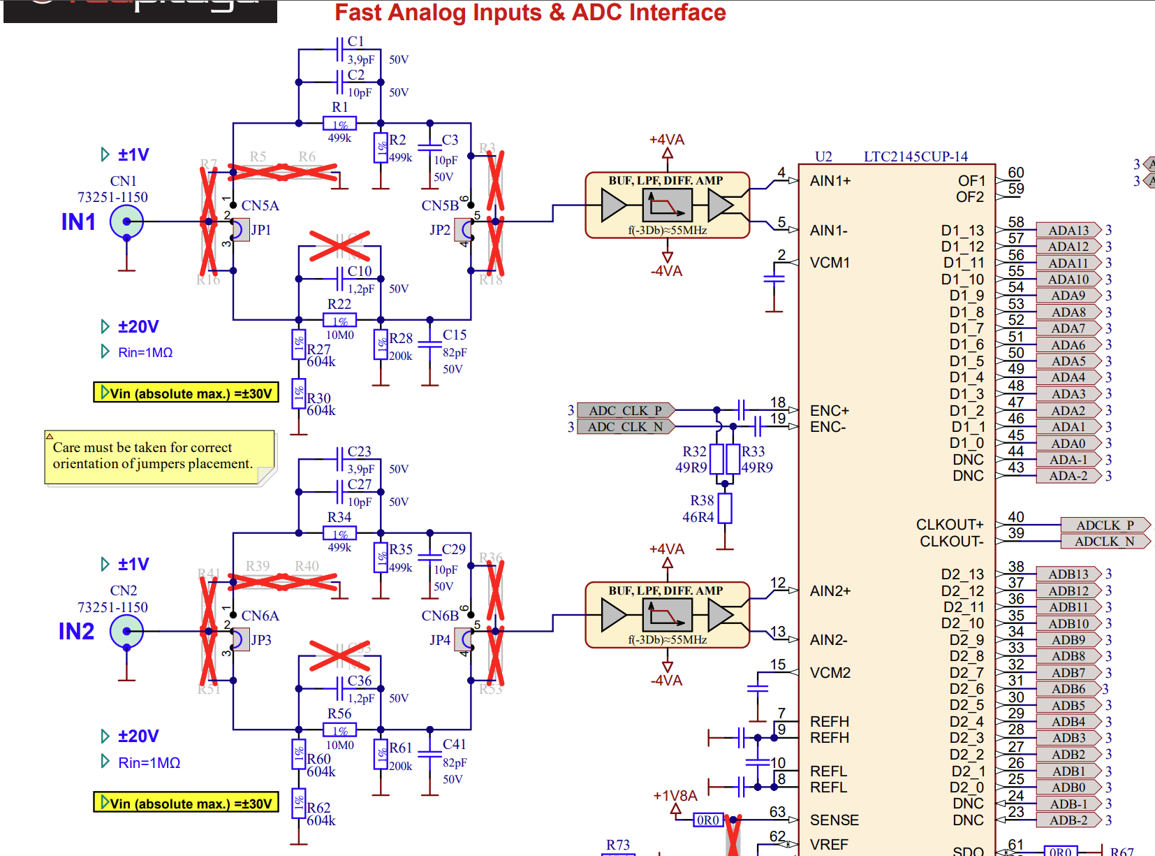
For more information, please refer to each board’s hardware documentation.
Input coupling
Fast analog inputs are DC coupled.
Performance Measurements
Input bandwidth
Jumper settings |
Bandwidth |
|---|---|
LV |
52.02 MHz (-3 dB) |
HV |
52.77 MHz (-3 dB) |
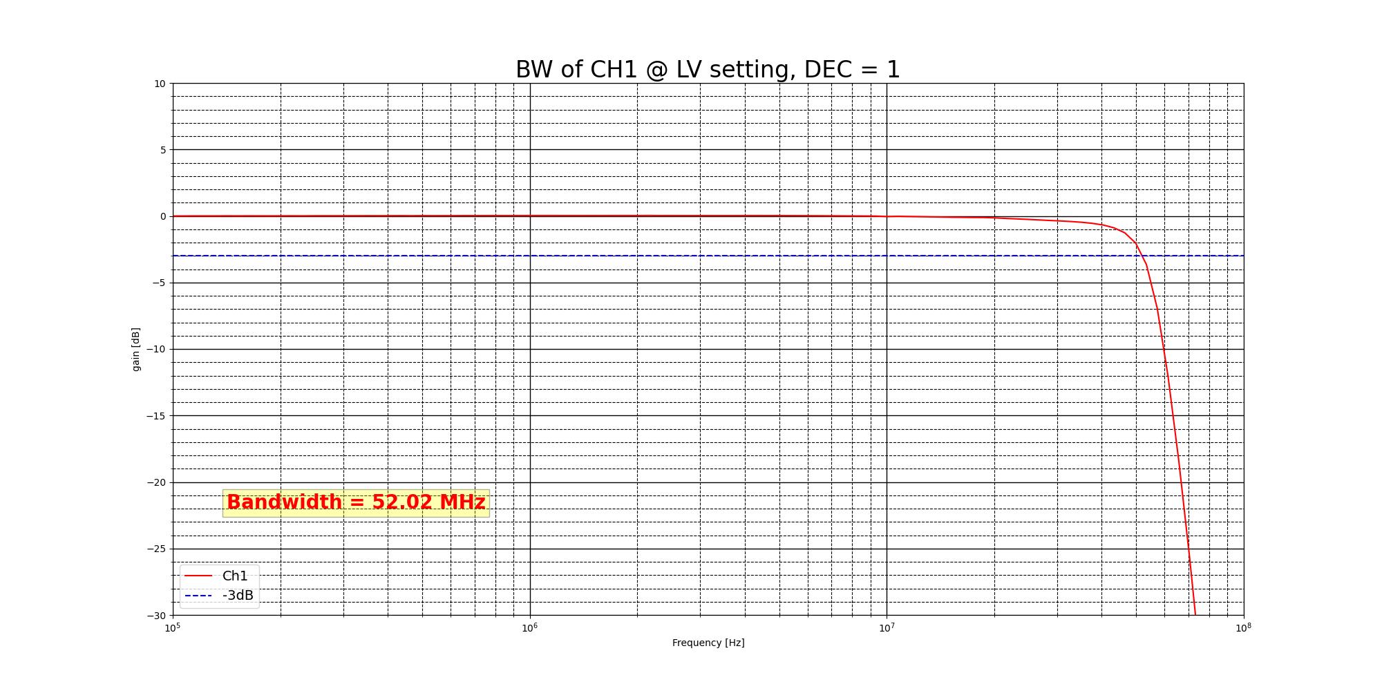
Bandwidth measurement of the input channel 1 in LV mode.
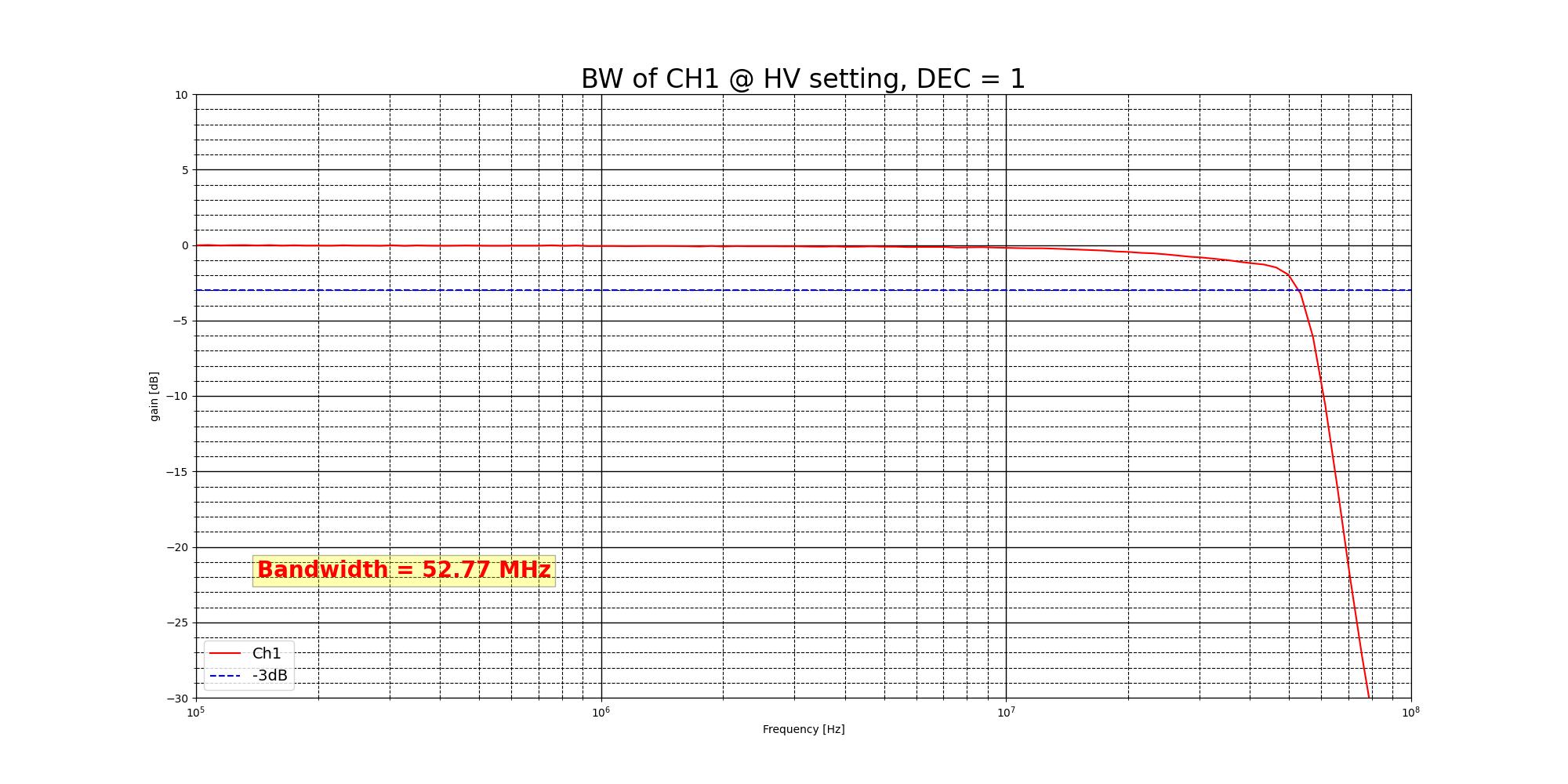
Bandwidth measurement of the input channel 1 in HV mode.
Input bandwidth flatness
The bandwidth flatness is <0.05 dB from DC to full (-3 dB) bandwidth on LV gain setting.
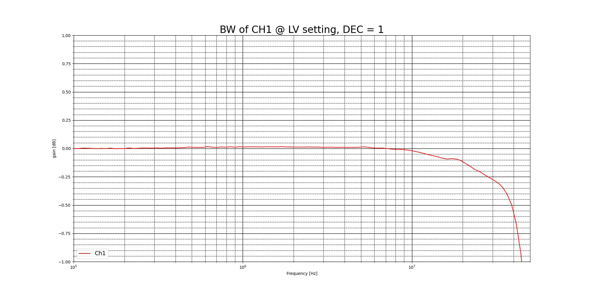
Bandwidth flatness measurement of the input channel 1 in LV mode.
Input crosstalk
Crosstalk measurements were performed between input channels 1 and 2 for both LV and HV modes.
Up to 30 MHz |
Above 30 MHz |
|||
|
|
|
|
|
LV |
>70 dB |
>80 dB |
>50 dB |
>50 dB |
HV |
40 dB |
55 dB |
>35 dB |
>40 dB |
|
|
|
|
|
LV |
>70 dB |
55 dB |
>55 dB |
50 dB |
HV |
70 dB |
55 dB |
>55 dB |
55 dB |
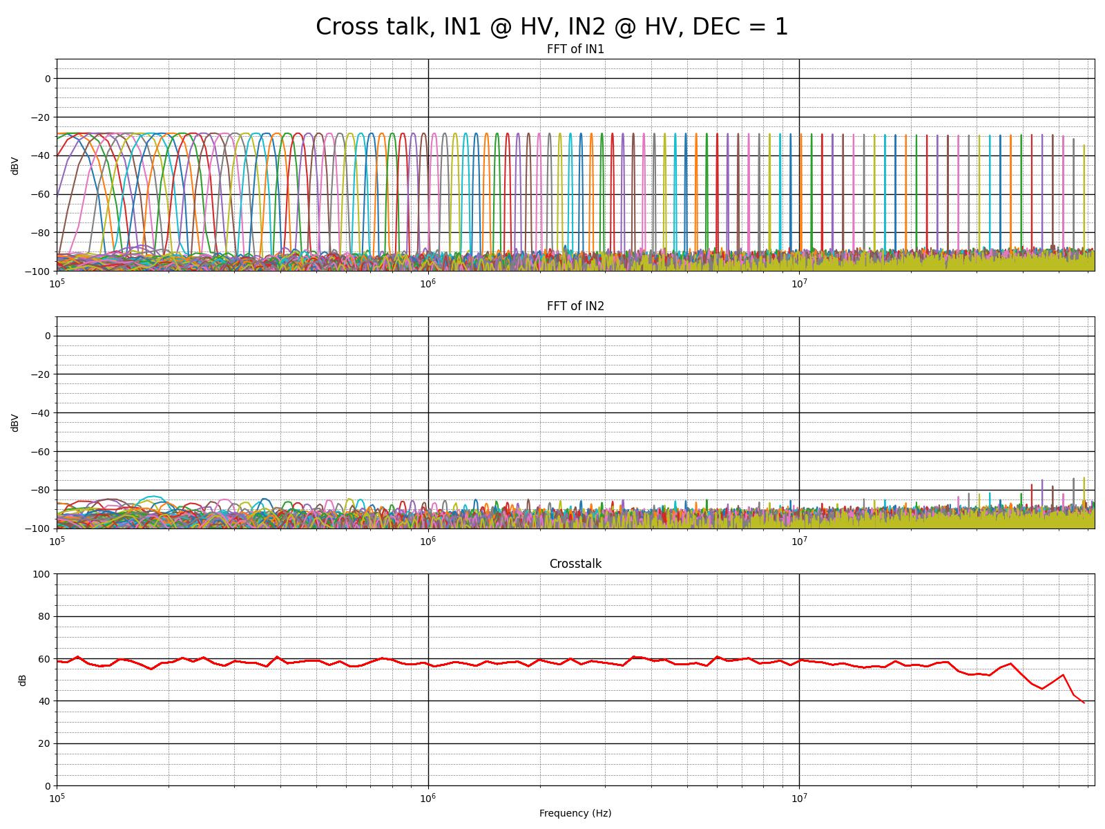
Crosstalk measurements between input channels 1 and 2 in HV mode.
Calibration
Analog inputs calibration
To calibrate the analog inputs, please refer to the Calibration guide.
Footnotes