SDR Module and HAMlab (obsolete)
Note
The Red Pitaya SDR module and accompanying HAMlab software are obsolete. The information provided here is for reference only.
For proper operation, the Red Pitaya SDR module requires a special HAMlab program that was part of the older HAMlab Red Pitaya OS images released between April 2017 and February 2019. The HAMlab program required to operate the SDR module is not available in the current OS images. The older OS images are available in the Red Pitaya archive. The Red Pitaya SDR module only supports STEMlab 125-14 board model.
HAMlab documentation
Note
The HAMlab documentation is available here: HAMlab documentation.
What is in the box?
The following accessories and materials are included with your Red Pitaya SDR transceiver module.
SDR Transceiver Module 160-10 10W
DC power cable with Anderson Power Pole™ connector
4 x SMA cable to connect C25 module to STEMlab 125-14 and antenna
Impedance transformer board
Other additional requirements
In addition to the accessories, software and cables supplied with the Red Pitaya SDR Transceiver Kit, you will need the following items
A HF antenna or dummy load with BNC
A good RF ground.
A stabilised DC 13.8 VDC, 3A Power supply.
SDR application requirements
A personal computer (PC) running Windows 7 or later. Either 32-bit or 64-bit operating systems are supported.
Start using Red Pitaya as a Radio Station - SDR transceiver
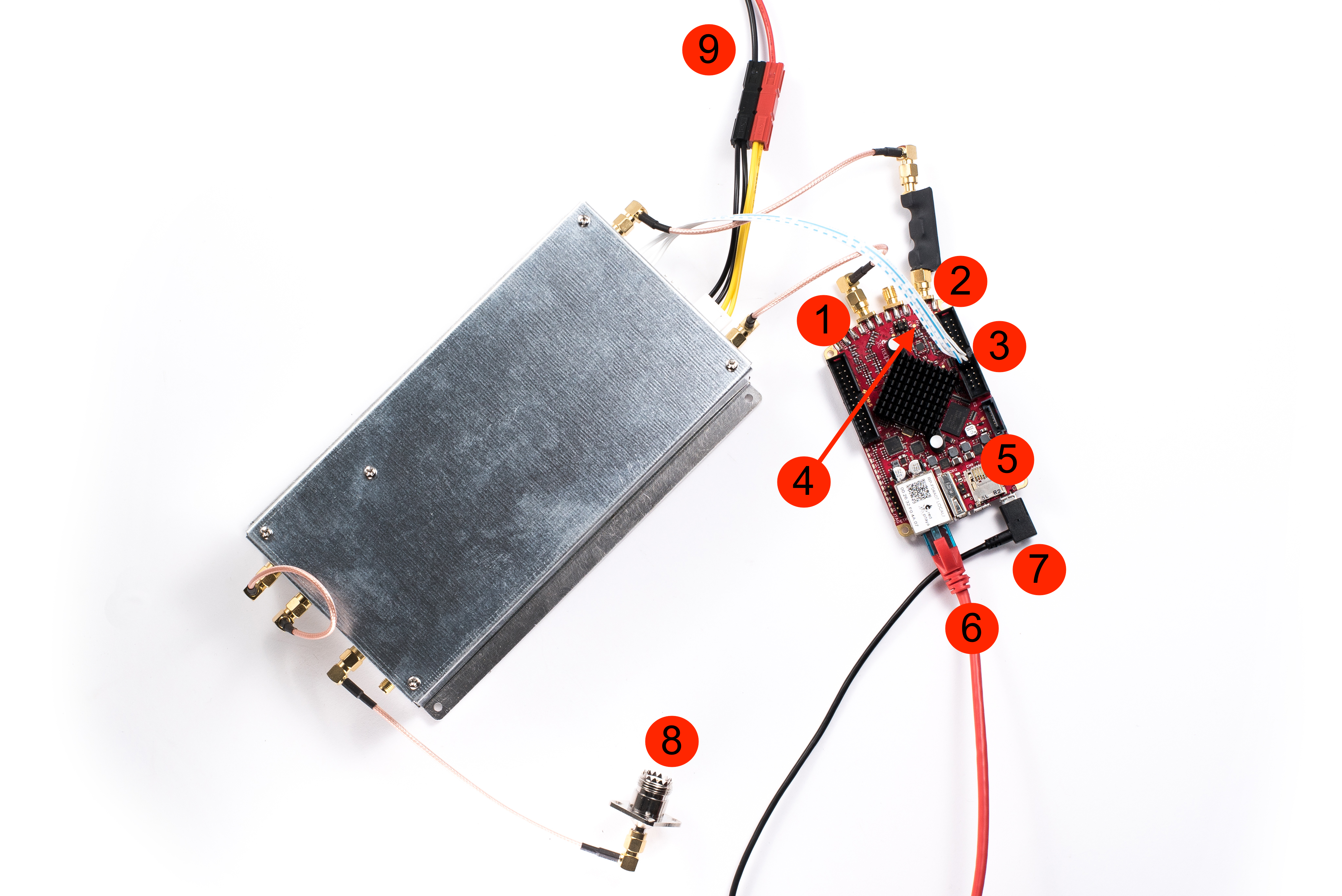
Connecting the cables
Note
Before connecting the Red Pitaya to the SDR transceiver module, switch off the Red Pitaya by unplugging the power cable.
Connect the TX of the SDR transceiver module to the OUT1 connector of the Red Pitaya.
Connect the RX of the SDR transceiver module to the Red Pitaya IN1 (note that this cable has a transformer).
Connect the control cable from the SDR transceiver to the Red Pitaya.
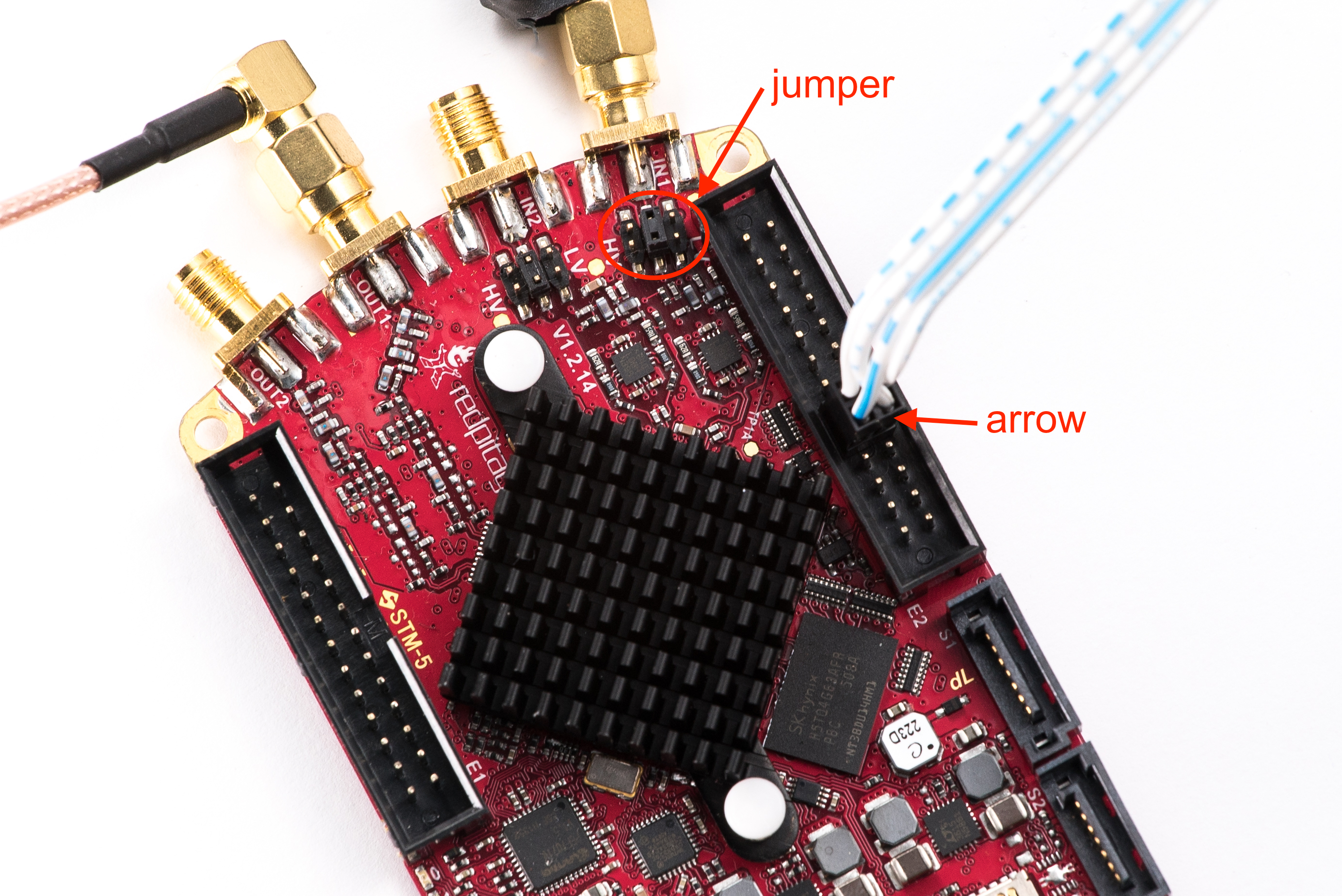
Figure 4.22 Identify the pin marked with an arrow and connect the cable as shown in the diagram above.
Check that the jumper is configured as shown in the figure above.
Check that the SD card is still inserted.
Check that your Ethernet cable is still connected.
Reconnect the power supply (5 V, 2 A) to restart the Red Pitaya.
Connect the antenna
Connect the SDR transceiver to the 13.8 V, 3 A power supply.
Note
The Red Pitaya SDR transceiver module should be powered by a DC 13.8V power supply capable of delivering at least 3A of constant current. Make sure it’s switched off before connecting it to the module with a DC power cable and an Anderson Power PoleTM connector (9). The RED wire is positive (+) and the BLACK wire is negative (-). Check that the colours and polarity are not mixed up!
Switch on the 13.8V power supply.
Power SDR installation and SDR configuration
Click here to download the Power SDR installation package.
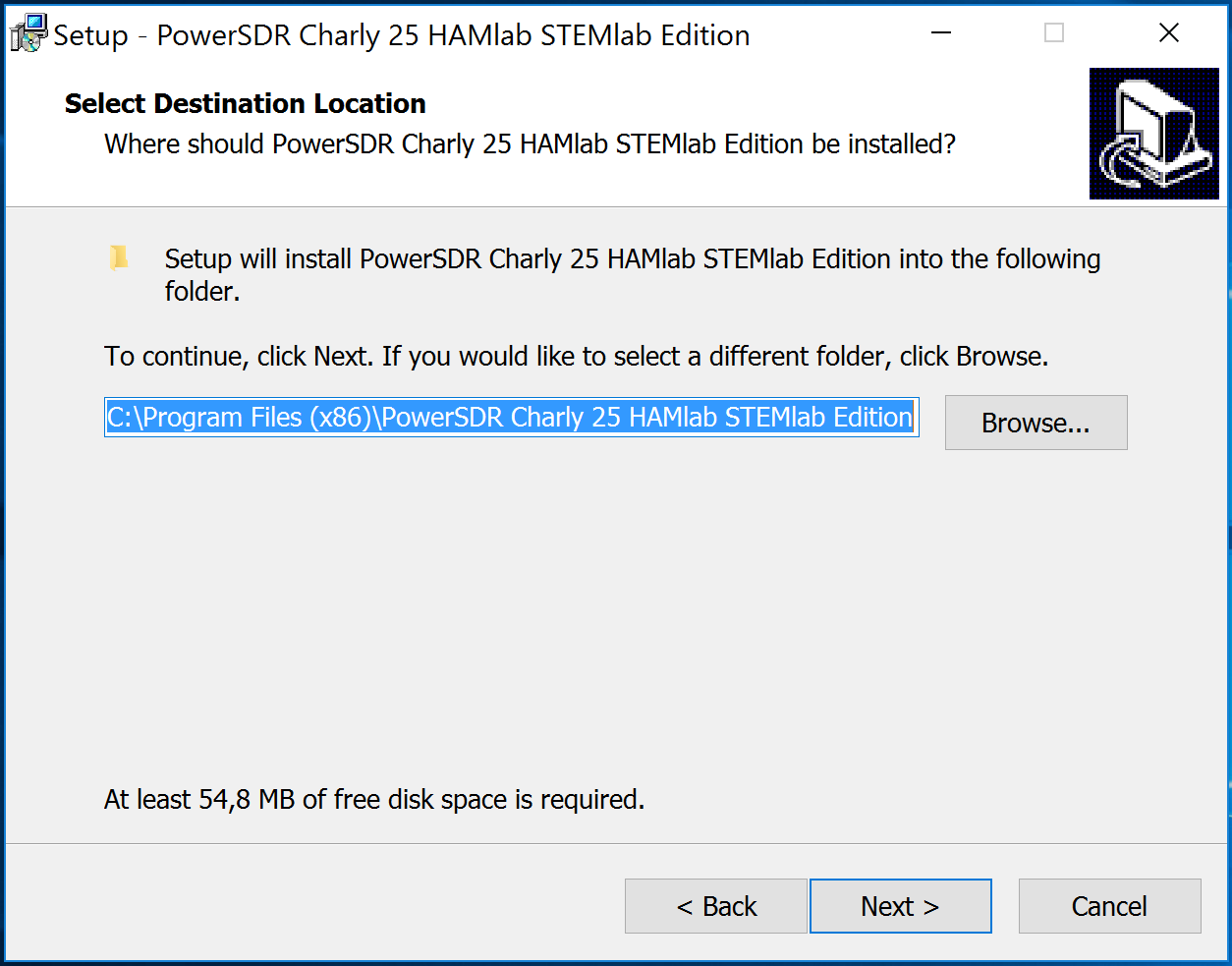
Start the installation by double-clicking the Setup_PowerSDR_STEMlab_HAMlab_Edition.exe file.
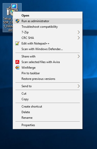
If you are asked for extended user rights during the installation, click Yes!. Running the installer with administrator rights will also work.
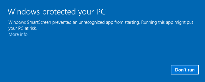
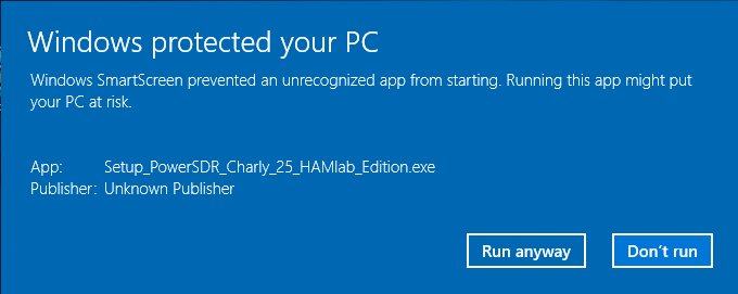
On Windows 10, you may receive a warning from an unknown publisher. You can continue with the installation by clicking More Info and then Run anyway.
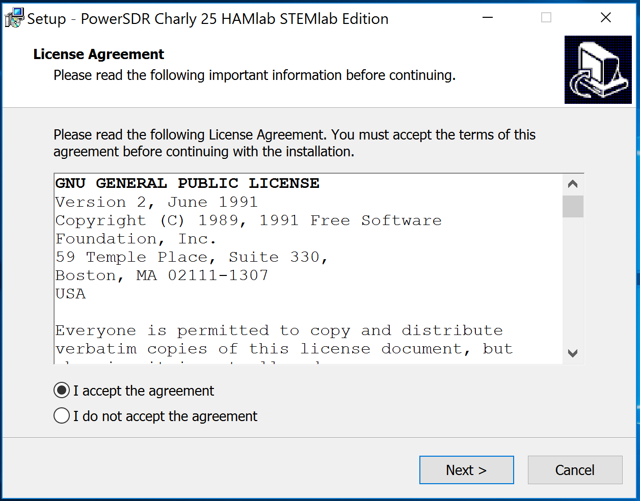
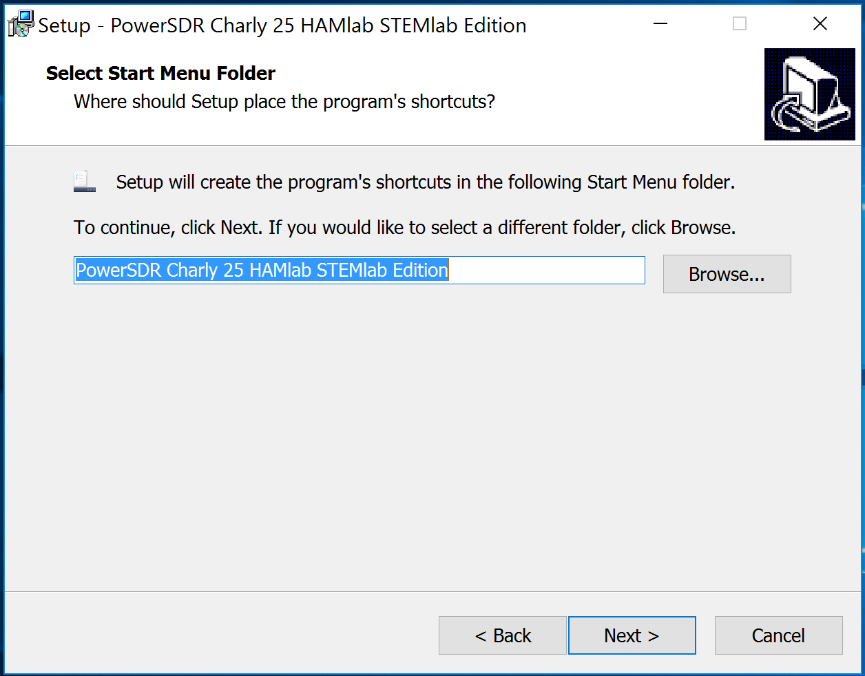
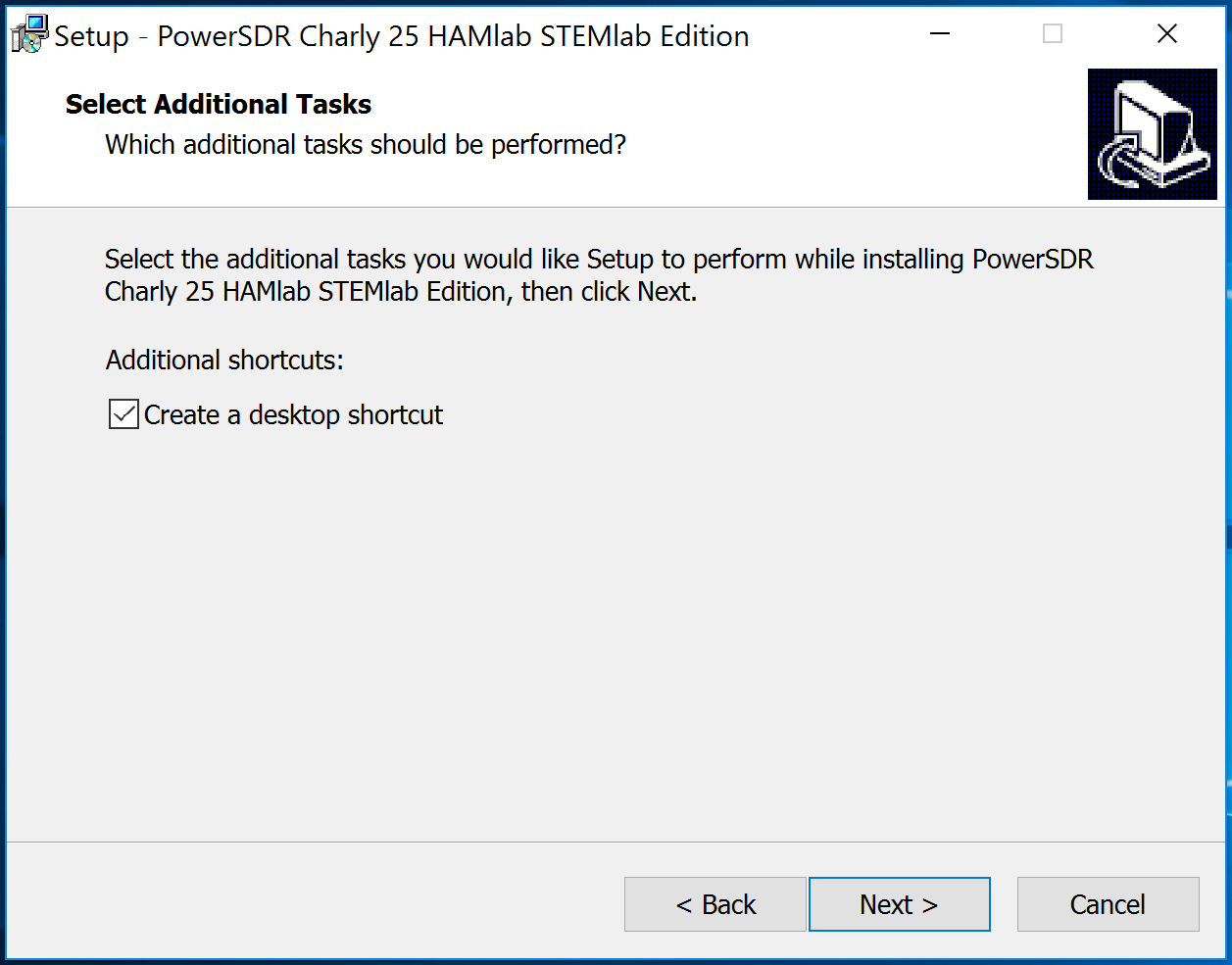
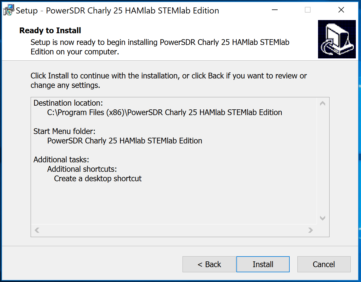
Follow the instructions in the setup routine and accept the licence agreements if asked.
At the end of the installation you will be asked if you want to run the PowerSDR software immediately. This is optional.
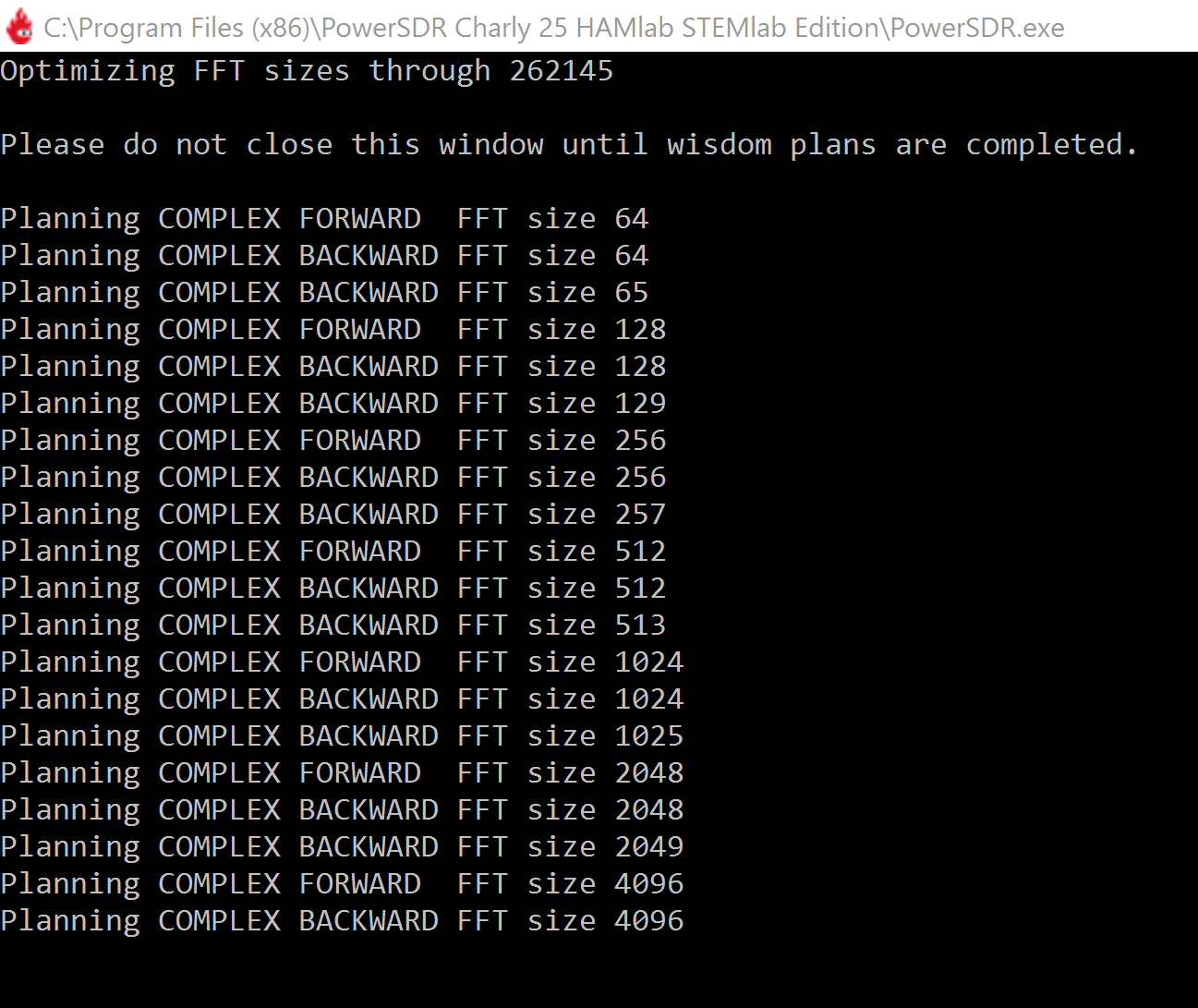
The PowerSDR software will start to calculate the FFT wisdom file, which may take a while depending on the CPU power of your computer. This will only happen once, even if you upgrade to a new version of the software in the future:
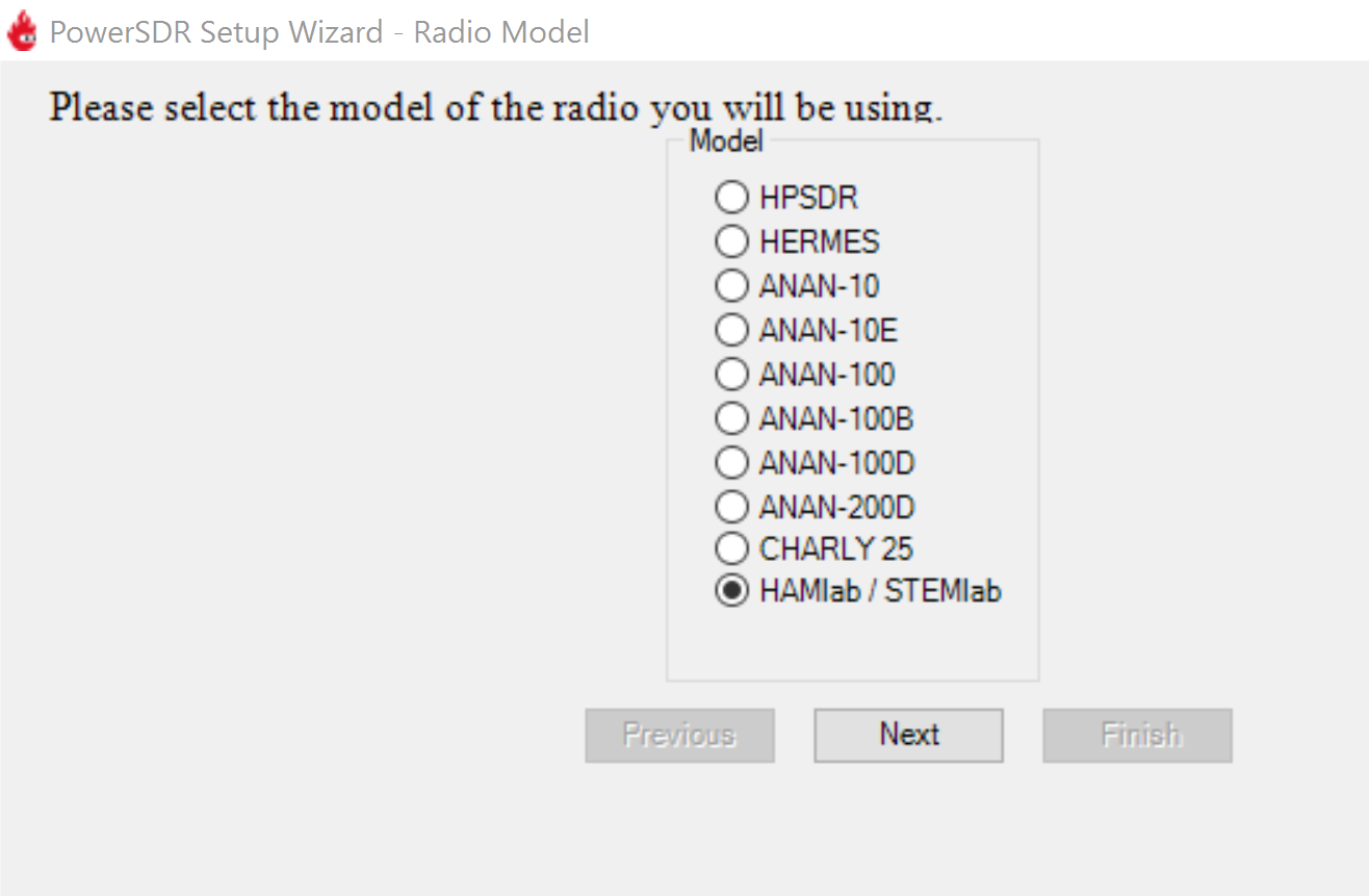
After starting the PowerSDR software, you will be guided through the PowerSDR software specific setup wizard to configure the software for use with your Red Pitaya. Select the HAMlab/RedPitaya radio model.
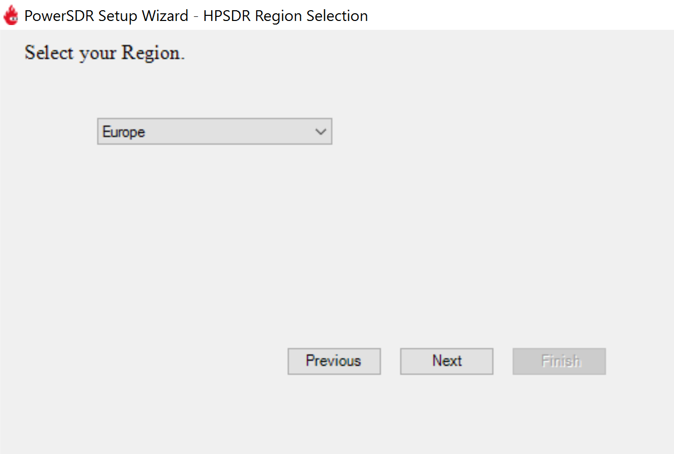
Select the region in which you will be using your Red Pitaya. This is important due to the different frequency ranges you are allowed to transmit in different countries around the world:
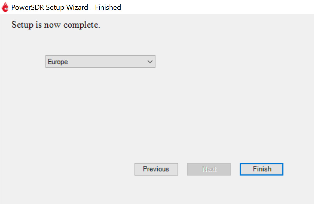
Your initial setup is complete. Click Finish.
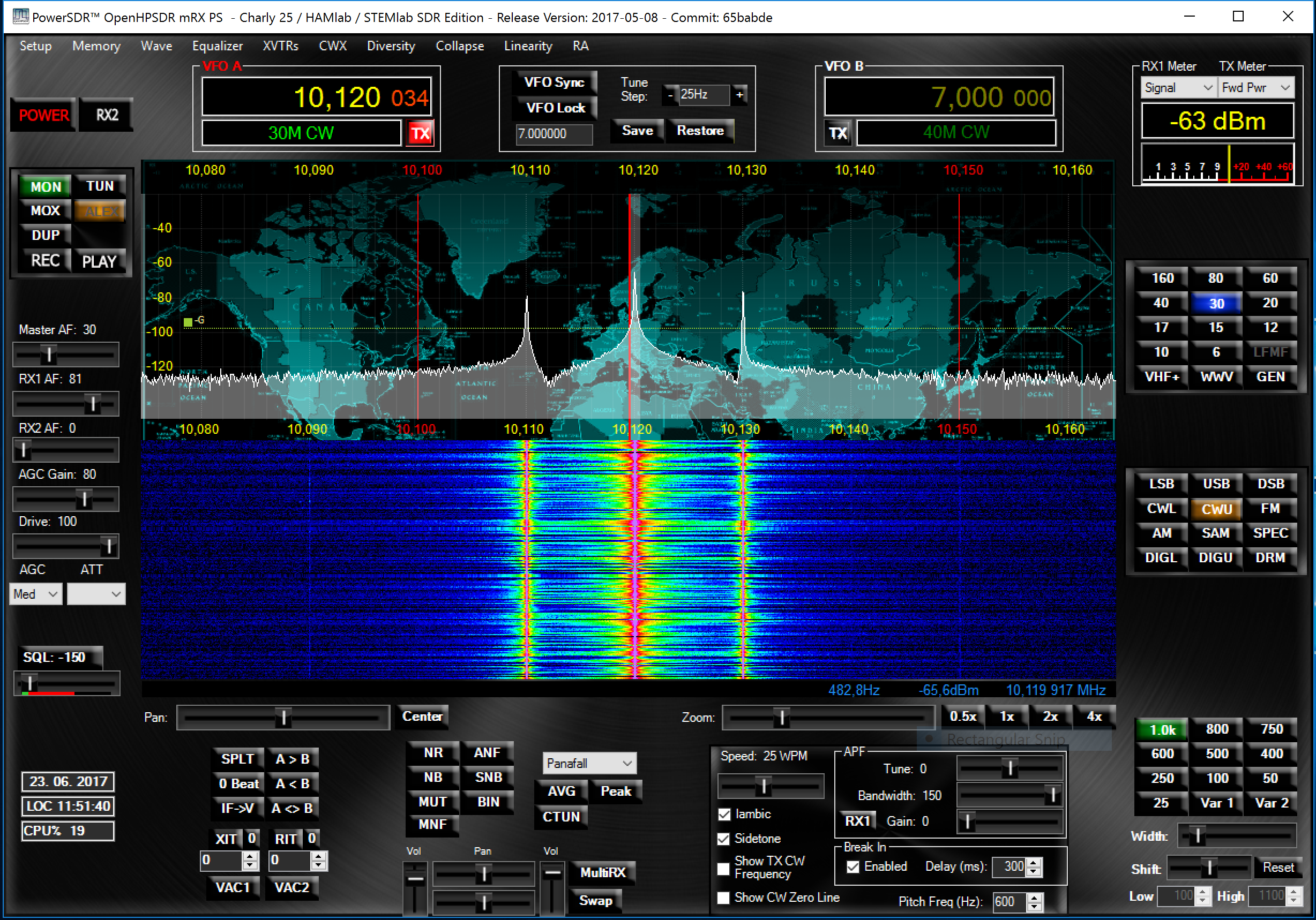
Click on Power to connect the Power SDR to Red Pitaya. The input signal should appear on the screen.
Specifications
Highlights |
|
|---|---|
Architecture: |
direct sampling / internal high performance 14-bit A/D and D/A 125 Msps converters (no sound card required) |
Band coverage: |
All band receiver and 160-6m transmitter |
Transmit power: |
up to 10 W |
Wideband Frequency Coverage: |
25 kHz - 62.25 MHz |
Connection to PC: |
1 Gbit ethernet or WIFI connection |
Software: |
Power SDR HAMlab edition |
Phones and MIC connection: |
available on the front panel |
Secondary Rx and Tx channel: |
available through back panel BNC connectors (RX2 IN, XVTX) |
CW key and paddle input: |
available through front panel jack connector |
General Specifications |
|
|---|---|
Antenna Connector: |
ANT1 and ANT2 available on SMA connectors. One cable with SMA to SO-239 UHF included. |
Antenna Impedance: |
50 Ohm unbalanced |
RF Output Power: |
Up to 10 W CW and SSB from 13.8 V input (max. 15 V) |
Maximum Interconnect Cable Length Ethernet: |
100 metres (328 feet) Category 5 cable |
Power connector: |
PowerPole |
Receiver Specifications |
|
|---|---|
Architecture: |
Direct Digital Sampling |
ADC Sampling Rate: |
125 Msps |
ADC Resolution: |
14 bits |
Wideband Frequency Coverage: |
25 kHz - 62.25 MHz |
MDS (min. detectable signal): |
MDS (typ)@ 500 Hz BW |
Preamp OFF at 14 MHz |
-113 dBm |
Preamp +15 dB at 14 MHz |
-130 dBm |
Preamp +30 dB at 50 MHz |
-135 dBm |
More MDS measurements. |
|
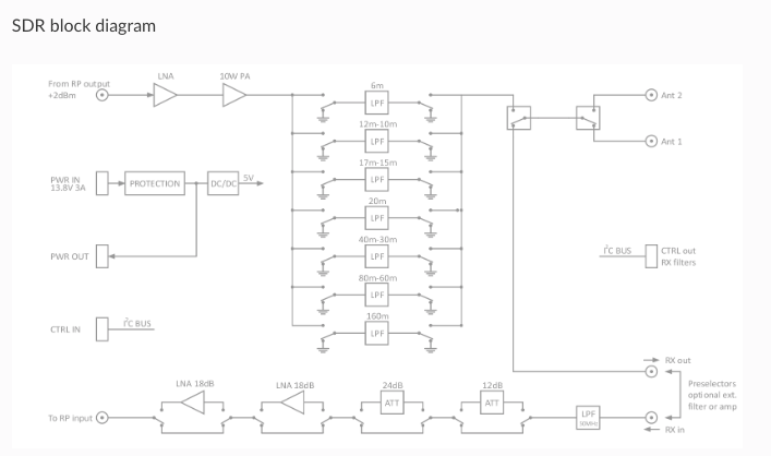
Preselectors: |
Not available |
User can also connect own preselectors/filters |
|
Transmitter Specifications |
|
|---|---|
Architecture: |
Direct Digital Up-conversion |
TX DAC Sampling Rate: |
125 Msps |
TX DAC Resolution: |
14 bits |
RF Output Power: |
up to 10 W CW and SSB at @ 13.8 V input voltage (max. 15 V) |
Transmitter Frequency Range: |
160 - 10 m (amateur bands only)* |
Low Pass PA Filter Bands: |
160 m / 80 m / 40 m / 30 m / 20 m / 17 m / 15 m / 12 m / 10 m / 6 m |
(possibility to changed it to any range 1.8 - 50 MHz) |
|
Emission Modes Types: |
A1A (CWU, CWL), J3E (USB, LSB), A3E (AM), F3E (FM), DIGITAL (DIGU, DIGL) |
DIGITAL (DIGU, DIGL) |
|
Harmonic Radiation: |
better than -45 dB |
3rd-Order IMD: |
better than -35 dB below PEP @ 14.2 MHz 10 Watts PEP |
Cooling: |
copper heat spreader |
Note
C25 also supports 6 m operation and has all the necessary output filters for 6 m. Anyhow, the STEMlab 125-14 output signal is not pure enough to comply with harmonic regulations for 6 m.
General Electrical specifications |
|
|---|---|
Power Requirements: |
+13.8 V DC nominal ± 15 % (Transmitter output specified at 13.8 V DC) |
Power Consumption: |
2 A |
Mechanical specifications |
|
|---|---|
Height: |
100 mm |
Width: |
340 mm |
Depth: |
215 mm |
Weight: |
5 kg |
Operating temperature: |
-10*C to +50*C |
Measurement instruments specifications
Oscilloscope |
|
|---|---|
Input channels |
2 |
Input channels connector |
BNC |
Bandwidth |
50 MHz |
Resolution |
14 bit |
Memory depth |
16384 Samples Max. |
Sampling Rat |
125 MS/s |
Input range |
±1 V or ±20 V |
Input coupling |
AC/DC |
Minimal Voltage Sensitivity |
±0.244 mV / ±2.44 mV |
External Trigger connector |
BNC |
Input coupling |
AC/DC |
Signal generator |
|
|---|---|
Output channels |
2 |
Output channels connector |
BNC |
Bandwidth |
50 MHz |
Resolution |
14 bit |
Signal buffer |
16384 Samples Max. |
Sampling Rate |
125 MS/s |
Output range |
± 1 V |
Frequency Range |
0 - 50 MHz |
Output impedance |
50 Ω |
External Trigger connector |
BNC |
Signal generator |
|
|---|---|
Input channels |
2 |
Input channels connector |
BNC |
Bandwidth |
0 - 62 MHz |
Dynamic Range |
-80 dBm |
Input noise level |
< -119 dBm/Hz |
Input range |
± 1 V |
Frequency Range |
0 - 50 MHz |
Input impedance |
1 MΩ / 10 pF |
Spurious frequency components |
-90 dBFS Typically |
Logic analyzer |
|
|---|---|
Input channels |
8 |
Max. sample rate |
125 MS/s |
Fastest input signal |
50 MHz |
Supported protocols |
I2C, SPI, UART |
Input voltage levels |
2.5 V - 5.5 V |
Threshold |
0.8 V for logic low
2.0 V for logic high
|
Input impedance |
100 kΩ 3 pF |
Sample depth |
1 MS (typical*) |
Trigger resolution |
8 ns |
Min. detectable pulse length |
10 ns |
Note
Acquired data is compressed; therefore, the size of data that can be captured depends on the activity of the signal on LA inputs. For I2C, SPI, and UART signals, 1MS is the typical sample depth. All instrumentation applications are web-based and don’t require the installation of any native software. Users can access them via a browser using their smartphone, tablet or a PC running any popular operating system (MAC, Linux, Windows, Android, and iOS).
Front panel controls and connections

SDR
Microphone connector (RJ45)
The HAMlab 80-10 10W front microphone connector (2) can support the Kenwood KMC 30 electret microphone or compatible types.

Figure 4.23 Front panel view microphone pinout
Pin |
Function |
|---|---|
1 |
NC |
2 |
8V DC |
3 |
Ground |
4 |
PTT |
5 |
Ground |
6 |
MIC |
7 |
NC |
8 |
NC |
CW Key / paddle jack
The CW key/paddle jack (3) is a 1/4 inch TRS phone plug.
Tip - DOT
Ring - DASH
The common is connected to the sleeve.
Note
3.3 V Max input.
For an iambic paddle, the tip is connected to the dot paddle, the ring is connected to the dash paddle, and the sleeve is connected to the common. For a straight key or a keyer output, connect to the tip and leave the ring floating. The common is connected to the sleeve.
Note
Currently, the keyer is not supported by software. Software support for it will be available in one of the upcoming software updates.
Phones
The HAMlab 80-10 10W supports a stereo headset with headphone ¼ inch TRS phone plug (4) . Mono or TS connector that grounds the “ring” portion of the connector should not be used!
Logic analyzer
0-7 are logic analyzer inputs.
G - common ground.
Note
The logic analyzer inputs (5) can only be used when the Logic Analyzer WEB app is running.
Oscilloscope
(6) - IN1
(7) - IN2
(8) - EXT. TRIG.
IN1, IN2 and EXT. TRIG. are oscilloscope inputs.
Note
These inputs are active and can be used only when the Oscilloscope+Signal generator WEB application is running.
Signal generator
(9) - OUT1
(10) - OUT2
OUT1 and OUT2 are signal generator outputs.
Note
These two outputs are active and can be controlled only when the Oscilloscope+Signal generator WEB application is running.
Note
To get the expected signals from the signal generator, the outputs must be 50 Ohm terminated.
Back panel controls and connections

ANT - TRANSCEIVER ANTENNA PORTS [1,2]
ANT1 (1) is SO-239 50 ohm connector, while ANT2 (2) is BNC 50 ohm connector.
A user can connect the transmitter output to ANT1 or ANT2 by properly connecting an SMA cable inside the chassis to one of the ANT connectors. Software switching between ANT1 and ANT2 is not available in the HAMlab 80-10 10W version.
Danger
THIS UNIT GENERATES RADIO FREQUENCY (RF) ENERGY. USE CAUTION AND OBSERVE PROPER SAFETY PRACTICES REGARDING YOUR SYSTEM CONFIGURATION. WHEN ATTACHED TO AN ANTENNA, THIS RADIO IS CAPABLE OF GENERATING RF ELECTROMAGNETIC FIELDS WHICH REQUIRE EVALUATION ACCORDING TO YOUR NATIONAL LAW TO PROVIDE ANY NECESSARY ISOLATION OR PROTECTION REQUIRED WITH RESPECT TO HUMAN EXPOSURE!
Danger
NEVER CONNECT OR DISCONNECT ANTENNAS WHILE IN TRANSMIT MODE. THIS COULD RESULT IN ELECTRICAL SHOCK OR RF BURNS TO YOUR SKIN, AS WELL AS DAMAGE TO THE UNIT.
AUX1
RX1 IN - direct feed to the first receiver pre-amp and attenuators.
RX1 OUT - an output from the antenna feeding
By default, the HAMlab 80-10 10W comes with a loopback cable connected from RX1 IN to RX1 OUT. Users can also use these two connectors to insert external filters or preamplifiers.
Note
This input is not protected by any ESD circuitry. Therefore, a device connected to the RX1 OUT Output is susceptible to possible damage by ESD from an EMP event if the connected device does not have adequate ESD protection circuitry.
Warning
Be aware that Preamp1 and Preamp2 are both wide-band amplifiers, covering the whole bandwidth of 55MHz. It is not recommended to use the preamps on a large antenna without a preselector connected (this would cause overload and intermodulation from strong broadcast signals outside the Amateur Radio Bands)!
AUX2
RX2 IN - secondary 50 Ohm receiver input that can be used as a second panadapter in Power SDR software or as a feedback signal for pre-distortions (Pure Signal tool).
XVTR (TX2 OUT) - secondary transmitter can be used to drive external PA. Max. output power is around 10 dBm @ 50ohm.
However, there is no support in HPSDR for a second TX output.
Power and Fuses
The HAMlab 80-10 10W is designed to operate from a 13.8 volt nominal DC supply and requires at least 4A.
Danger
This unit must only be operated with the electrical power described in this manual. NEVER CONNECT THE +13.8 VDC POWER CONNECTOR DIRECTLY TO AN AC OUTLET. This may cause a fire, injury, or electrical shock.
The HAMlab 80-10 10W requires 13.8 VDC @ 4 A measured at the radio in order to transmit maximum wattage. Multiple power cable connections between the power supply and the HAMlab 80-10 10W, a poorly regulated power supply, undersized power cable, and very long power cable lengths will result in a voltage drop, especially under load. Any voltage deviation from 13.8 VDC will result in a lower power output than the 10W nominal specification.
For best results, select a linear or switching power supply that is well regulated and free of internally generated radio frequency noise. “Birdies” generated by a poorly filtered supply can often appear as signals in the Power SDR Panadapter display.
The Anderson Powerpole™ connector contains 45 Amp pins to minimize voltage drop during transmit. The RED connection should be connected to the positive (+) lead of the power source. The BLACK, connection should be connected to the negative (-) lead of the power source.
If you choose to use your own Powerpole cabling, be sure to properly size the wire and the Powerpole connector to minimise voltage drop during transmit. An excessive voltage drop can cause lower transmit power output levels.
There are two internal fuses in the HAMlab. One protects the whole system while the other one is just for the transceiver. If you ever need to replace the internal fuse, remove the top cover and the shield of the power board.
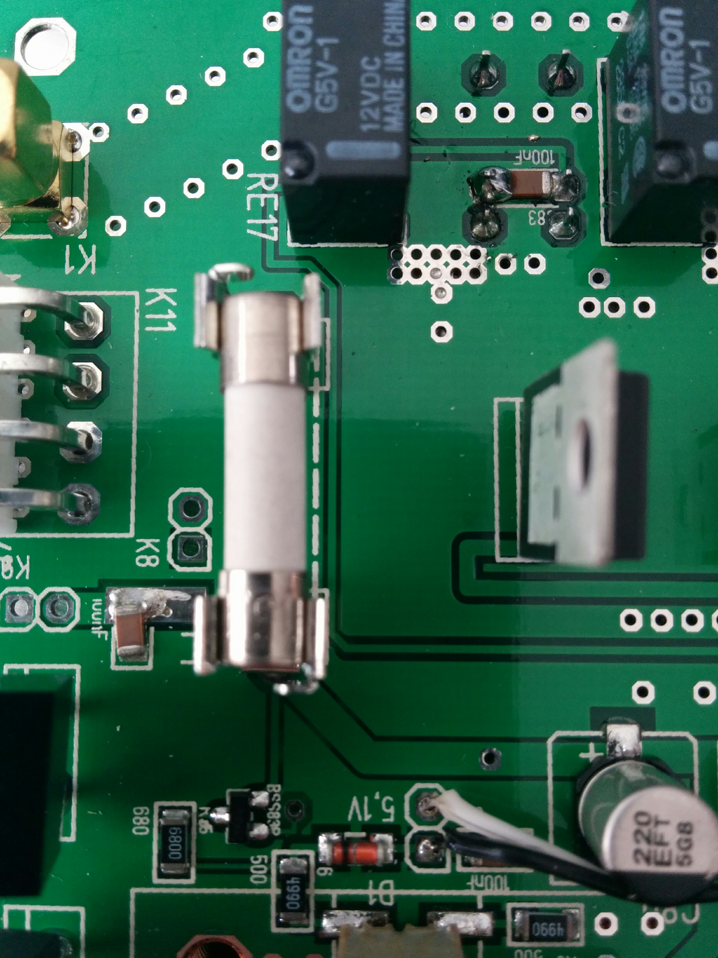
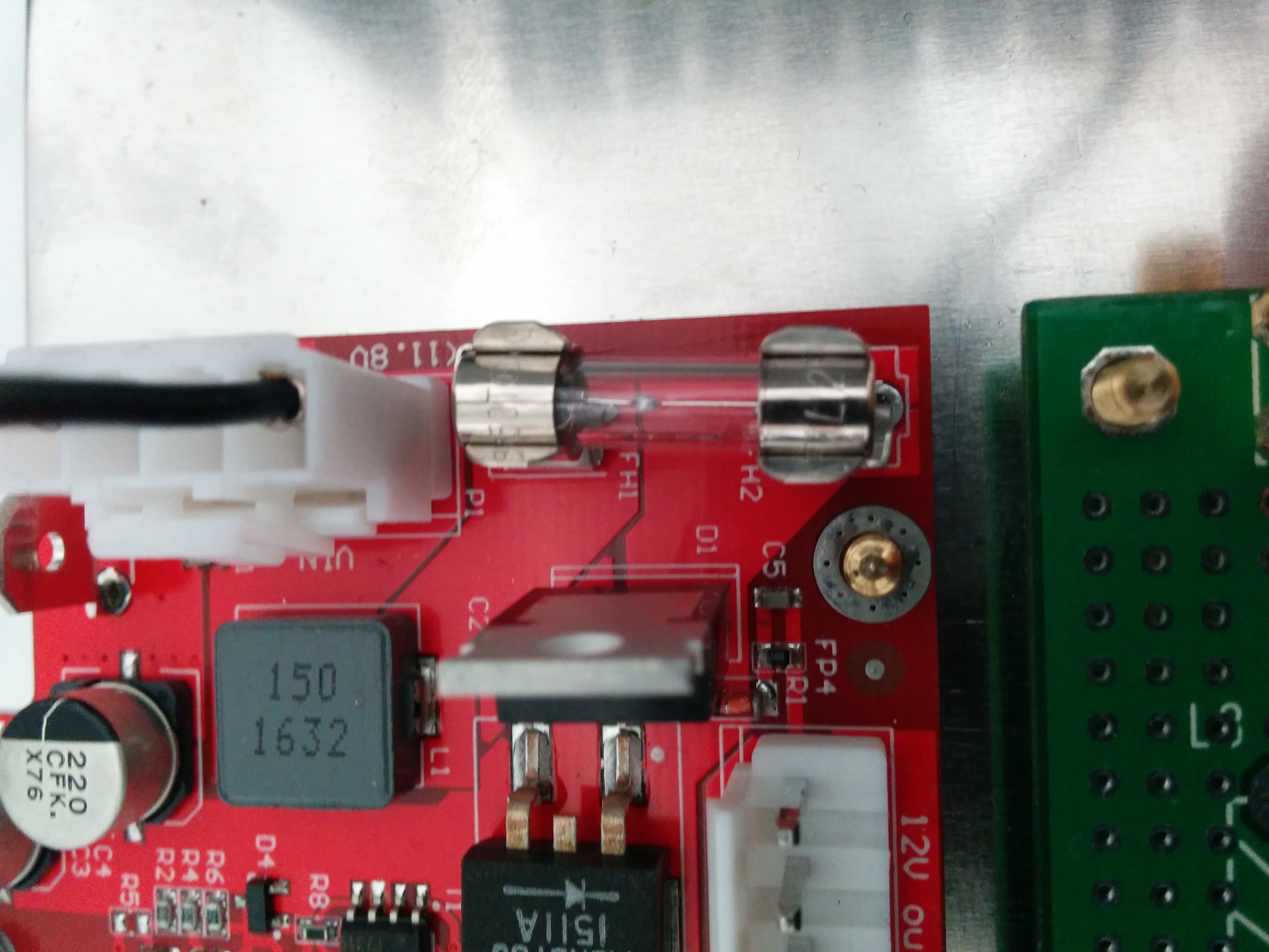
Danger
FUSE CURRENT RATING SHOULD EXCEED 3.15 A! FAILURE TO USE THIS SAFETY DEVICE PROPERLY MAY RESULT IN DAMAGE TO YOUR RADIO, POWER SUPPLY, OR CREATE A FIRE RISK.
Chassis ground
This is a thumbscrew for attaching an earth ground to the chassis of the radio. Grounding is the most important safety enhancement you can make to your shack. Always ground the HAMlab to your station RF ground using high quality wiring with the length being as short as possible. Braided wire is considered the best for ground applications. Your station ground should be a common point where all grounds come together. You will likely be using a PC and a DC power source, so be sure to ground these devices together as well.
AUDIO
Audio USB connector
USB 2.0 Cable - A-Male to Mini-B must be used to connect the HAMlab audio sound card with the PC in order to be able to use the phone, MIC, and speaker connector for voice communication.
Note
The USB connector is only available on the HAMlab 80-10 10W model. For new models, audio codecs are used and audio is transferred over ethernet.
Speaker connector - 1/8” TRS stereo connector can be used to connect stereo powered computer speakers.
Note
Do not use a mono or TS connector that grounds the “ring” portion of the connector.
CTRL
DB9 connector is used to control external equipment.
PTT OUT relay is connected between pins 6 and 7.
Note
Other pins are, at the moment, not in use and should be left unconnected.
DATA
LAN - This is the network connection to the HAMlab. It is an auto-sensing 100 megabit or 1 gigabit Ethernet port that enables you to connect HAMlab to your local network or directly to a PC.
USB - This USB port is used to connect a WIFI dongle when a user would like to connect to HAMlab wirelessly.
Note
The recommended Wi-Fi USB dongle is the Edimax EW7811Un. In general, all Wi-Fi USB dongles that use the RTL8188CUS chipset should work.
SD card - The HAMlab software is running from the SD card.
Note
HAMlab comes with a pre-installed SD card with HAMlab OS. An upgrade can be done using the OS upgrade application from the HAMlab application menu, and there is no need to remove the SD card. Therefore, users should remove the SD card and reinstall SD card software only if the system gets corrupted or stops working due to SD card failure. In this case, only the official HAMlab OS should be installed on the SD card for proper operation.