Red Pitaya

Documentation Contents

  • 1. What is Red Pitaya?
  • 2. Quick start
    • 2.1. Identify your board model
      • 2.1.1. List of Red Pitaya board models
      • 2.1.2. How to identify your board model
      • 2.1.3. Visual identification guide
        • Gen 2 boards
        • Original Gen boards
    • 2.2. What do I need before I start?
    • 2.3. Connect to Red Pitaya
      • 2.3.1. Identify your board model
      • 2.3.2. Connection requirements
      • 2.3.3. Connection steps (all board models)
      • 2.3.4. Find your Red Pitaya’s web address
        • Method 1: Using the hostname (recommended)
        • Method 2: Using the IP address
      • 2.3.5. Success! You’re connected
      • 2.3.6. Troubleshooting
    • 2.4. Update Red Pitaya OS
    • 2.5. Prepare SD card
      • 2.5.1. Installation steps
      • 2.5.2. Installation instructions for Windows, Linux and macOS
        • Windows
        • Linux
        • macOS
    • 2.6. SD card advanced guide
      • 2.6.1. OS Versions
        • Latest 2.00 OS
        • 1.04 OS
        • Older OS versions
        • Nightly Builds
      • 2.6.2. Command-line installation
        • Linux
        • macOS
      • 2.6.3. Red Pitaya OS partitions
        • Delete partitions on the SD card
      • 2.6.4. Manual ecosystem upgrade
      • 2.6.5. Nightly build installation guide
        • Updating nightly build ecosystem
      • 2.6.6. Installing older OS on new boards
      • 2.6.7. Resize file system
    • 2.7. QSPI eMMC board connection
      • 2.7.1. Features
      • 2.7.2. Contents
      • 2.7.3. Hardware requirements
      • 2.7.4. Installing the QSPI eMMC board
      • 2.7.5. Booting Red Pitaya with QSPI eMMC board
      • 2.7.6. QSPI and eMMC boot options
      • 2.7.7. Hardware and software specifications
    • 2.8. Red Pitaya Aluminium Case Assembly
      • 2.8.1. Components
      • 2.8.2. Compatibility
      • 2.8.3. Assembly Instructions
    • 2.9. Red Pitaya Acrylic Case Assembly
      • 2.9.1. Components
      • 2.9.2. Compatibility
      • 2.9.3. Assembly Instructions
    • 2.10. Red Pitaya heatsink interface setup
      • 2.10.1. Compatibility
      • 2.10.2. Components
      • 2.10.3. Before the assembly
      • 2.10.4. Assembly instructions
    • 2.11. FAQ
      • 2.11.1. General troubleshooting
      • 2.11.2. Application-specific troubleshooting
      • 2.11.3. Troubleshooting procedure
        • 1. Update the OS/firmware
        • 2. Status LEDs
        • 3. Network connection
        • 4. Serial console boot log
        • 5. Hardware connections
        • 6. Web applications
        • 7. Advanced Troubleshooting
      • 2.11.4. Connectivity
        • How to get started with Red Pitaya?
        • How to connect to Red Pitaya in a few simple steps?
        • Red Pitaya not booting anymore?
        • Red Pitaya is constantly rebooting?
        • How to connect the external clock to Red Pitaya?
        • How can I make sure that my Red Pitaya has access to the internet?
        • How can I make sure that Red Pitaya is connected to the same network as my computer/tablet/smartphone?
        • Is Red Pitaya connected to my local network?
        • How to find the Red Pitaya URL if it is not written on the sticker?
        • Slow Wi-Fi connection?
        • Wi-Fi dongle not detected?
      • 2.11.5. OS
        • How to update & upgrade OS?
        • Is Red Pitaya not booting even after OS update?
        • Is Red Pitaya failing to update?
        • Balena Etcher archive corrupted error?
      • 2.11.6. Applications & Web Interface
        • How can I start using RP measurement applications?
        • My device shows the wrong measurements. How can I calibrate it?
        • I am not getting any signal on the inputs or outputs of my Red Pitaya?
        • Problems with OS update application, and accessing the marketplace?
        • Web interface not functioning properly, or freezing?
        • Undesired disconnections?
        • An application is not working?
        • Lock-in PID applications
      • 2.11.7. Software
        • How can I acquire data with Red Pitaya?
        • How can I generate data with Red Pitaya?
        • How to control Red Pitaya remotely using LabVIEW, MATLAB, and Python?
        • Where can I find the ecosystem, software, and FPGA images?
        • How to start with FPGA development?
        • Are there any restrictions on installing Python packages?
      • 2.11.8. Hardware
        • Where can I find Red Pitaya schematics, 3D models (.step), and important components?
        • Are the FPGA, ADC and DAC synchronised?
        • Is there a hardware difference between the STEMlab 125-14 and the ISO17025 versions?
        • Is there a hardware difference between normal boards and OEM versions?
        • What is the difference between STEMlab 125-14 and STEMlab 125-14 Low Noise?
        • Is the STEMlab 125-14 board in the “Calibrated kit” calibrated?
        • What are the main differences between different Red Pitaya boards?
        • What is the bandwidth of the Red Pitaya boards?
      • 2.11.9. Gen 2 FAQ
      • 2.11.10. How to report a problem?
  • 3. Applications and Features
    • 3.1. Introduction to data acquisition and generation with Red Pitaya
      • 3.1.1. Oscilloscope and other applications
        • Running multiple web applications simultaneously
      • 3.1.2. SCPI commands
        • SCPI Acquisition
        • SCPI generation
      • 3.1.3. API commands (C++, Python)
      • 3.1.4. Streaming application
      • 3.1.5. Deep Memory Acquisition (DMA)
      • 3.1.6. Custom acquisition and generation (FPGA)
    • 3.2. Applications
      • 3.2.1. Oscilloscope & Signal Generator
        • Features
        • Specifications
        • Source code
      • 3.2.2. Arbitrary Waveform Manager
        • Features
        • Uploading custom waveforms
        • Source code
      • 3.2.3. Spectrum Analyzer
        • Features
        • Specifications
        • Source code
      • 3.2.4. Logic Analyzer
        • Top Settings Menu
        • Digital signal settings
        • Trigger settings
        • Cursors
        • Hardware/Connections
        • Specifications
        • How to decode bus data?
        • Source code
      • 3.2.5. Bode Analyzer
        • Features
        • Top settings menu
        • Measurement control panel
        • Calibration
        • Specifications
        • Source code
      • 3.2.6. Impedance Analyzer
        • Features
        • Top settings menu
        • Measurement control panel
        • How to use the impedance analyzer
        • Source code
      • 3.2.7. LCR meter
        • Connecting the LCR module
        • Features
        • Source code
      • 3.2.8. Data stream control
        • Overview
      • 3.2.9. RF Signal Recording and Playback script
        • How it works
        • Features
        • Requirements
        • Installation
        • Configuration
        • Usage
        • Troubleshooting
        • FAQ
        • Source code
      • 3.2.10. SDR applications
        • SDR Transceiver compatible with HPSDR
        • SDR Receiver compatible with HPSDR
        • SDR transceiver
        • macOS compatibility
        • Author & Source
      • 3.2.11. Vector Network Analyzer
        • What do I need before I start?
        • Start using Red Pitaya as a Vector Network Analyser
        • Perform calibration and start measuring
      • 3.2.12. PyPRL
        • What do I need before I start?
        • Compatibility
        • Install & run PyRPL
        • Author & Source
      • 3.2.13. Marketplace and contributed apps
        • Overview
        • Available Applications
        • Marketplace Access (Legacy)
        • Application Documentation
    • 3.3. System tools
      • 3.3.1. System Info
        • General OS and Ecosystem info
      • 3.3.2. Network Manager
        • Wired
        • Wireless
      • 3.3.3. Software update manager
        • Updating the OS
        • Software update manager troubleshooting
        • Other ways to update the ecosystem and Red Pitaya Linux OS
      • 3.3.4. Calibration
        • Overview
        • When to Calibrate
        • Required Equipment
        • Quick Reference Guide
        • Calibration Methods
        • Command Line Calibration
        • Known Issues
    • 3.4. Multiboard Synchronisation
      • 3.4.1. How can I control synchronised boards?
      • 3.4.2. X-Channel 2.0 (Click Shield) Synchronisation
        • Setup
        • Oscillator
        • External Clock
        • Hardware specifications
      • 3.4.3. X-Channel Synchronisation
        • Setup
        • Cable orientation
        • Alternative uses of S1 and S2 connectors
        • Board compatibility
        • Example - signal acquisition (streaming client)
      • 3.4.4. Code examples
      • 3.4.5. Multiboard synchronisation Q&A
        • Can I synchronise multiple different Red Pitaya board models with the Click Shields?
        • What is the difference between Red Pitaya X-channel System and Red Pitaya X-channel 2.0 (Click Shield) Synchronisation?
    • 3.5. Programming and remote-control tools
      • 3.5.1. SCPI server (MATLAB, LabVIEW, or Python)
        • Quick start
        • Starting SCPI server manually
        • Starting SCPI server at boot time
        • How do SCPI commands work?
      • 3.5.2. C++ and Python Applications
        • Version compatibility
        • API overview
        • Working with C++ Applications
        • Working with Python Applications
        • Running applications at boot
        • Available Libraries
        • API Command Reference
        • API Examples
      • 3.5.3. Jupyter Lab
        • Features
        • Hardware - Sensor extension module
        • Examples
      • 3.5.4. Deep Memory Mode (DMM)
        • Deep Memory Acquisition (DMA)
        • Deep Memory Generation (DMG)
        • Changing reserved memory
        • API functions
        • API Code Examples
      • 3.5.5. List of supported SCPI & API commands
        • Initialization commands
        • Board control commands
        • LEDs and GPIOs
        • Analog Inputs and Outputs
        • Phase locked loop
        • Daisy chain clocks and triggers
        • Signal Generator
        • Acquisition
        • Deep Memory Mode (DMM)
        • LCR mode
        • UART
        • SPI
        • I2C
        • CAN
        • Status LEDs
        • Temperature protection and power
      • 3.5.6. Examples
        • Digital
        • Analog
        • Generating signals at RF outputs
        • Acquiring signals at RF inputs
        • Generating and Acquiring signals at RF inputs/outputs
        • Multi-board signal acquisition and generation
        • Deep Memory Acquisition and Generation
        • Digital communication interfaces
        • LCR meter example
        • Logic Analyzer
        • Streaming Examples
        • Web application examples
      • 3.5.7. Known SCPI & API issues and changes by OS version
        • How to find all available SCPI commands per OS version?
        • 2.05-37
        • 2.04-35
        • 2.00-30
        • 2.00-23
        • 2.00-18
        • 2.00-15
        • 1.04-28
        • 1.04-18 and older
    • 3.6. Command-line tools
      • 3.6.1. Signal generator utility
        • Source code
      • 3.6.2. Signal acquisition utility
        • Source code
      • 3.6.3. Spectrum analyzer utility
        • Source code
      • 3.6.4. Bode Analyzer
        • Source code
      • 3.6.5. LCR meter
        • Source code
      • 3.6.6. Daisy utility
        • Source code
      • 3.6.7. Streaming application utility
        • Data streaming
        • Source Code
      • 3.6.8. Monitor utility
        • Accessing system registers
        • Accessing FPGA registers
        • Source code
      • 3.6.9. LED control utility
        • Source code
      • 3.6.10. Calibration utility
        • New calibration storage format
        • Old calibration storage format
        • Source code
      • 3.6.11. Ecosystem update utility
        • Software requirements
        • Usage
        • Examples of use
        • Other ways to update the ecosystem and Red Pitaya Linux OS
        • Source code
      • 3.6.12. E3 I2C controller utility
        • Software requirements
        • Usage
        • Source code
      • 3.6.13. Overlay Utility (FPGA Configuration)
        • Overview
        • Command Help
        • Basic Usage
        • Command Syntax
        • Usage Examples
        • Verification
        • Common Issues
        • File Structure
        • Converting Bitstream Files
        • Advanced Usage - fpgautil
        • Related Documentation
        • Source Code
      • 3.6.14. Other useful information related to command-line tools
        • Saving data buffers
        • Copying data - Linux users
        • Copying data - Windows users
    • 3.7. Supported features and apps by Red Pitaya model
      • 3.7.1. Gen 2
      • 3.7.2. Original Generation
  • 4. Developer’s guide
    • 4.1. Hardware
      • 4.1.1. Understanding Product Names
      • 4.1.2. Understanding Generations
        • Gen 2 vs Original Generation
      • 4.1.3. Identify Your Board
      • 4.1.4. Products
        • Second generation boards
        • Original boards
        • Extension modules
        • Discontinued
        • Obsolete
      • 4.1.5. Specifications & Comparisons
        • General hardware specifications
        • Product comparison tables
      • 4.1.6. Known hardware issues
        • Known Hardware Issues (Gen 2)
        • Known Hardware Issues (Original Gen)
      • 4.1.7. Performance & Measurements
        • Original Gen Performance & Measurements
      • 4.1.8. Certificates
        • Certificates
    • 4.2. Software
      • 4.2.1. Introduction to Red Pitaya Software Development
        • 1. Understanding Red Pitaya Software Architecture
        • 2. Development Approaches
        • 3. Development Workflow
        • 4. Prerequisites
        • 5. Getting Help
        • 6. Next Steps
      • 4.2.2. Getting Started
        • Console Access
        • C++ Compiler and Make Utility Setup
        • Windows Subsystem for Linux Setup
      • 4.2.3. Application Development
        • Running C++ and Python Applications
        • Compiling Streaming client applications
        • Create your own WEB applications
      • 4.2.4. System Development
        • Build Red Pitaya ecosystem
        • Build Red Pitaya OS
        • E3 module - software
      • 4.2.5. System Configuration & Integration
        • Network
        • Service Management
        • General purpose input output
        • SPI interface
        • Interfacing SPI TFT displays with touch
        • Remote software deployment
      • 4.2.6. Troubleshooting
        • OS Version Compatibility
        • Known Software Issues
    • 4.3. FPGA section
      • 4.3.1. Navigating the FPGA Documentation
      • 4.3.2. Typical FPGA Development Workflow
      • 4.3.3. What’s in each section
        • Getting Started with FPGA Development
        • FPGA Tutorials
        • FPGA projects
        • Advanced FPGA Topics
        • Registers
  • 5. Customization services
Red Pitaya
  • 3. Applications and Features
  • 3.5. Programming and remote-control tools
  • 3.5.6. Examples
  • Digital
  • Blink

Blink

Description

This example shows how to control one of the Red Pitaya on-board LEDs and make it blink.

Required hardware

  • Red Pitaya device

../../../_images/redpitaya_led0_blink.gif

Required software

  • 2.00-23 or higher OS

Note

This code is written for 2.00-23 or higher OS. For older OS versions, please check when specific commands were released (a note is added to each command introduced in 2.00 or higher verisons).

SCPI Code Examples

Code - MATLAB ®

The code is written in MATLAB. TCP client communication is used to establish socket communication with Red Pitaya, then SCPI commands are sent to configure the various Red Pitaya peripherals. Copy the code below into the MATLAB editor, save the project and press the Run button. Tested on MATLAB 2024b.

%% Define Red Pitaya as TCP/IP object

IP = ('rp-f0a235.local');               % Input IP of your Red Pitaya...
port = 5000;
RP = tcpclient(IP, port);               % creates a TCP client object

%% Open connection with your Red Pitaya
RP.ByteOrder = "big-endian";
configureTerminator(RP, 'CR/LF');       % defines the line terminator (end sequence of input characters)

%% Send SCPI command to Red Pitaya to turn ON LED1
for i=1:5
    writeline(RP,'DIG:PIN LED1,1');     % Peripheral_Unit: Unit_Part/function:subfunction/settings
    % readline()                        % reading data
    % writeread()                       % send a command and read the reply

    pause(1);                           % Set time of LED ON

    % Send SCPI command to Red Pitaya to turn OFF LED1
    writeline(RP,'DIG:PIN LED1,0');

    % other possible commands:
    % DIG:PIN:DIR <dir>,<gpio>
    % DIG:PIN <pin>,<state>
    % DIG:PIN? <pin> => <state>         % Acquire status or read data

    pause(1);
end

%% Close connection with Red Pitaya
clear RP;

Code - Python

#!/usr/bin/env python3

import sys
import time
import redpitaya_scpi as scpi

IP = 'rp-f066c8.local'
rp = scpi.scpi(IP)

if (len(sys.argv) > 2):
    led = int(sys.argv[2])
else:
    led = 0

print ("Blinking LED["+str(led)+"]")

period = 1 # seconds

while 1:
    time.sleep(period/2.0)
    rp.tx_txt('DIG:PIN LED' + str(led) + ',' + str(1))
    time.sleep(period/2.0)
    rp.tx_txt('DIG:PIN LED' + str(led) + ',' + str(0))

rp.close()

Note

The Python functions are accessible with the latest version of the redpitaya_scpi.py document available on our GitHub. The functions represent a quality-of-life improvement as they combine the SCPI commands in an optimal order and also check for improper user inputs. The code should function at approximately the same speed without them.

For further information on functions please consult the redpitaya_scpi.py code.
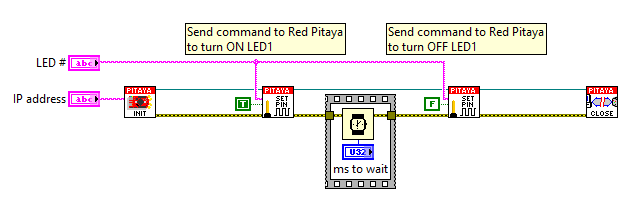
Code - LabVIEW

../../../_images/Blink_LV.png
  • Download Example

API Code Examples

Note

The API code examples don’t require the use of the SCPI server. Instead, the code should be compiled and executed on the Red Pitaya itself (inside Linux OS). Instructions on how to compile the code and other useful information are here.

Code - C++ API

#include <stdio.h>
#include <stdlib.h>
#include <unistd.h>

#include "rp.h"

int main (int argc, char **argv) {
    int unsigned period = 1000000; // uS
    int unsigned led;

    // index of blinking LED can be provided as an argument
    if (argc > 1) {
        led = atoi(argv[1]);
    // otherwise LED 0 will blink
    } else {
        led = 0;
    }
    printf("Blinking LED[%u]\n", led);
    led += RP_LED0;

    // Initialization of API
    if (rp_Init() != RP_OK) {
        fprintf(stderr, "Red Pitaya API init failed!\n");
        return EXIT_FAILURE;
    }

    int unsigned retries = 1000;
    while (retries--){
        rp_DpinSetState(led, RP_HIGH);
        usleep(period/2);
        rp_DpinSetState(led, RP_LOW);
        usleep(period/2);
    }

    // Releasing resources
    rp_Release();

    return EXIT_SUCCESS;
}

Code - Python API

#!/usr/bin/python3

import time
import rp

period = 1      # period in secodns

# Initialize the interface
rp.rp_Init()

#####! Choose one of two methods, comment the other !#####
#! METHOD 1: Interacting with Registers direclty
while 1:
    time.sleep(period/2.0)
    rp.rp_LEDSetState(0b00000001)     # or 0b00000001
    time.sleep(period/2.0)
    rp.rp_LEDSetState(0b00000000)     # or 0


#! METHOD 2: Using Macros
while 1:
    time.sleep(period/2.0)
    rp.rp_DpinSetState(rp.RP_LED0, rp.RP_HIGH)
    time.sleep(period/2.0)
    rp.rp_DpinSetState(rp.RP_LED0, rp.RP_LOW)

# Release resources
rp.rp_Release()
Previous Next

© Copyright 2026, Red Pitaya d.o.o.

Built with Sphinx using a theme provided by Read the Docs.