QSPI eMMC module - Software
The QSPI eMMC module is an extension board that provides secure boot options and power management for Red Pitaya boards. This guide covers software setup, programming the onboard STM32 microcontroller, and firmware configuration.


Overview
Module capabilities
Single button power on/off of Red Pitaya board
QSPI and eMMC boot options
STM32 microcontroller provides:
Red Pitaya power control
Safe shutdown management
Watchdog timer functionality
Boot media selection (SD card/eMMC)
Arduino C++ firmware with open source code
8 high-speed differential pairs (16 GPIOs) directly connected to Zynq FPGA
For hardware specifications and pinout details, refer to the hardware section.
Prerequisites
Hardware requirements
Required components:
Red Pitaya STEMlab 125-14 Pro Gen 2 or STEMlab 125-14 Pro Z7020 Gen 2 board
QSPI eMMC module
Red Pitaya power supply (the module is powered through the Red Pitaya board)
Programming hardware (choose one method):
ST-Link/V2 programmer (recommended) + 5-wire 2.54mm to 2.0mm pitch cable
USB to micro USB cable for DFU programming
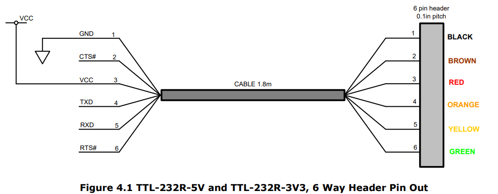
TTL to USB Serial Converter cable (3.3V, e.g., TTL-232R-3V3) - currently not supported
The ST-Link/V2 programmer is the recommended method as it provides the most reliable programming experience for STM32 microcontrollers.
Note
The QSPI eMMC module connects to Red Pitaya via the E3 connector, which controls power and boot media selection. The module must be connected to a powered Red Pitaya board during programming.
Compatibility
The QSPI eMMC module is compatible with:
STEMlab 125-14 Pro Gen 2
STEMlab 125-14 Pro Z7020 Gen 2
Note
High-speed differential pairs are only supported on the STEMlab 125-14 Pro Z7020 Gen 2 board.
Software requirements
The STM32 microcontroller (STM32L412K8T6) can be programmed using various development environments:
Arduino IDE + STM32CubeProgrammer (covered in this guide)
STM32CubeIDE
Visual Studio Code + PlatformIO
Visual Studio Code + STM32 libraries and plugins
This guide uses Arduino IDE and STM32CubeProgrammer, but you can use any preferred STM32 development method.
Hardware Setup
Connection methods
ST-Link/V2 programmer (recommended)
Connect the ST-Link/V2 to your computer via USB. A red LED should illuminate on the programmer.
If drivers don’t install automatically, download them from the ST official website.
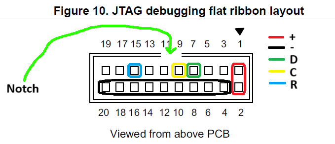
Connect the 5-wire jumper cable between the CN7 connector on the QSPI eMMC module (2.0mm pitch) and the ST-Link/V2 programmer (2.54mm pitch).
USB connection (DFU mode)
Connect a USB to micro USB cable between the CN4 connector on the QSPI eMMC module and your computer.
UART connection (currently not supported)
Connect the TTL to USB Serial Converter cable between the UART port on the QSPI eMMC module and your computer. Ensure TX and RX pins are connected correctly.
Note
Not all USB ports may work reliably. If you experience connection issues, try different USB ports or verify cable connections using the ST-Link/V2 programmer connection test.
Software Installation
This section covers installing the development tools required to program the QSPI eMMC module.
Installing Arduino IDE
Download the latest Arduino IDE from the Arduino official website.
Open Arduino IDE and navigate to File → Preferences.
In the Additional Boards Manager URLs field, add:
https://github.com/stm32duino/BoardManagerFiles/raw/main/package_stmicroelectronics_index.json
Click OK to close the Preferences window.
Navigate to Tools → Board → Boards Manager.
In the Boards Manager, search for “STM32”.
Install the latest version of STM32 MCU based boards by STMicroelectronics.
Restart Arduino IDE.
Installing STM32CubeProgrammer
Download STM32CubeProgrammer from the ST official website.
Note
You will need to create an ST account to download the software.
Run the installer and ensure all necessary drivers are installed during setup.
Launch STM32CubeProgrammer to verify installation.
Configuring Arduino IDE
Board configuration
Open Arduino IDE and navigate to Tools → Board.
Select STM32 MCU based boards → Generic STM32L4 series.

Under Tools → Board Part Number, select Generic L412K8Tx.

Under Tools → USB Support, select CDC (generic ‘Serial’ supersede U(S)ART).
Under Tools → Upload Method, select your programming method:
STM32CubeProgrammer (SWD) - for ST-Link V2 programmer
STM32CubeProgrammer (DFU) - for USB to micro USB cable
STM32CubeProgrammer (Serial) - for USB to Serial cable (currently not supported)
Recommended Tools settings:

Opening the firmware
Download the QSPI eMMC module firmware from the GitHub: RedPitaya/RedPitaya-Examples/tree/dev/E3_module_code repository and open the Arduino sketch (.ino file) in Arduino IDE.
Firmware Configuration
The QSPI eMMC module firmware requires specific configuration to function correctly with the STM32L412K8T6 microcontroller. Follow these steps carefully when setting up your Arduino project.
Step 1: Create build options file
Create a file named build.opt in the same directory as your Arduino sketch with the following content:
-HAL_I2C_MODULE_ENABLED
-HAL_UART_MODULE_ENABLED
-HAL_PCD_MODULE_ENABLED
-HAL_HCD_MODULE_ENABLED
These definitions enable I2C, UART, and USB peripheral support in the STM32 HAL library. The build system automatically includes this file during compilation.
Step 2: Include required libraries
Add these library includes at the beginning of your Arduino sketch:
#include <PeripheralPins.h>  // Pin definitions for STM32L412K8T6
#include <Wire.h>             // I2C communication functions
Step 3: Redefine peripheral pin mappings
The default pin mappings in the STM32 library must be overridden because not all pins are available on the STM32L412K8T6 package. Add these pin map definitions at the beginning of your sketch:
/* REDEFINE DEFAULT PINMAP */
const PinMap PinMap_I2C_SDA[] = {
  { PB_4, I2C3, STM_PIN_DATA(STM_MODE_AF_OD, GPIO_NOPULL, GPIO_AF4_I2C3) },
  { PB_7, I2C1, STM_PIN_DATA(STM_MODE_AF_OD, GPIO_NOPULL, GPIO_AF4_I2C1) },
  { NC, NP, 0 }
};

const PinMap PinMap_I2C_SCL[] = {
  { PA_7, I2C3, STM_PIN_DATA(STM_MODE_AF_OD, GPIO_NOPULL, GPIO_AF4_I2C3) },
  { PB_6, I2C1, STM_PIN_DATA(STM_MODE_AF_OD, GPIO_NOPULL, GPIO_AF4_I2C1) },
  { NC, NP, 0 }
};

const PinMap PinMap_UART_TX[] = {
  { PA_2, USART2, STM_PIN_DATA(STM_MODE_AF_PP, GPIO_PULLUP, GPIO_AF7_USART2) },
  { NC, NP, 0 }
};

const PinMap PinMap_UART_RX[] = {
  { PA_3, USART2, STM_PIN_DATA(STM_MODE_AF_PP, GPIO_PULLUP, GPIO_AF7_USART2) },
  { NC, NP, 0 }
};

const PinMap PinMap_USB[] = {
  { PA_11, USB, STM_PIN_DATA(STM_MODE_AF_PP, GPIO_NOPULL, GPIO_AF10_USB_FS) },  // USB_DM
  { PA_12, USB, STM_PIN_DATA(STM_MODE_AF_PP, GPIO_NOPULL, GPIO_AF10_USB_FS) },  // USB_DP
  { NC, NP, 0 }
};
Warning
Pin redefinitions are critical for proper operation. Omitting these will cause the microcontroller to malfunction or fail to initialize peripherals correctly.
Step 4: Define pin names
Define readable names for all I/O pins used by the QSPI eMMC module:
/* PIN DEFINITIONS */
#define PWR_ON_CN_PIN (PA0)     // Power On signal from CN2 connector
#define PWR_ON_PB_PIN (PA1)     // Power On signal from P-ON button
#define UART_TX_PIN (PA2)       // UART TX (not connected - shares bus with I2C1)
#define UART_RX_PIN (PA3)       // UART RX (populate R17, R18, R3, R4 for DIO12 connection)
#define E3_WDT_KICK_PIN (PA4)   // Watchdog timer signal from Red Pitaya
#define E3_SHDN_PIN (PA5)       // Shutdown signal to Red Pitaya
#define PS_POR_PIN (PA6)        // Power-On Reset signal (read-only)
#define PWR_ON_PIN (PB1)        // Power supply control output
#define LED_RED_PIN (PA8)       // Red LED control
#define LED_GREEN_PIN (PA9)     // Green LED control
#define USB_N_PIN (PA11)        // USB D- data line
#define USB_P_PIN (PA12)        // USB D+ data line
#define UC_SWDIO_PIN (PA13)     // SWD data line for programming
#define UC_SWCLK_PIN (PA14)     // SWD clock line for programming
#define I2C0_SCL_PIN (PB6)      // I2C0 clock connected to Red Pitaya
#define I2C0_SDA_PIN (PB7)      // I2C0 data connected to Red Pitaya
#define I2C1_SCL_PIN (PA7)      // I2C1 clock (not connected - shares bus with UART)
#define I2C1_SDA_PIN (PB4)      // I2C1 data (populate R3, R4 for DIO12 connection)
Step 5: Declare communication interfaces
Initialize UART and I2C interfaces at the global scope:
// UART and I2C interface declarations
HardwareSerial Serial1(UART_RX_PIN, UART_TX_PIN);
TwoWire Wire0(I2C0_SDA_PIN, I2C0_SCL_PIN);  // I2C0 bus for Red Pitaya communication
// TwoWire Wire1(I2C1_SDA_PIN, I2C1_SCL_PIN);  // I2C1 (not currently supported)
Note
I2C1 and UART interfaces are currently not supported as there is no physical connector on the QSPI eMMC module.
Step 6: Initialize pins in setup()
Configure all I/O pins in your setup() function:
void setup() {
    // Configure pin directions
    pinMode(PWR_ON_CN_PIN, INPUT);    // External power control input
    pinMode(PWR_ON_PB_PIN, INPUT);    // Button power control input
    pinMode(E3_WDT_KICK_PIN, INPUT);  // Watchdog signal from Red Pitaya
    pinMode(E3_SHDN_PIN, OUTPUT);     // Shutdown signal to Red Pitaya
    pinMode(PS_POR_PIN, INPUT);       // Power-on reset status from Red Pitaya
    pinMode(PWR_ON_PIN, OUTPUT);      // Power control output
    pinMode(LED_GREEN_PIN, OUTPUT);   // Green LED
    pinMode(LED_RED_PIN, OUTPUT);     // Red LED

    // Initialize LED states
    LED_off(LED_RED_PIN);
    LED_off(LED_GREEN_PIN);

    // Initialize communication interfaces
    Serial1.begin(115200);                  // UART at 115200 baud
    Wire0.begin(I2C_ADDR);                  // I2C0 as slave at I2C_ADDR
    Wire0.setClock(400000);                 // I2C speed: 400 kHz
    Wire0.onReceive(I2C0_receive_handler);  // Register I2C receive callback
    Wire0.onRequest(I2C0_request_handler);  // Register I2C request callback

    /*
    // I2C1 initialization (not currently implemented)
    Wire1.begin(I2C_ADDR);
    Wire1.setClock(400000);
    Wire1.onReceive(I2C1_receive_handler);
    Wire1.onRequest(I2C1_request_handler);
    */
}
Warning
All configuration steps above are mandatory. Missing any step will result in improper microcontroller operation.
Programming the Module
Important
The QSPI eMMC module must be connected to a powered Red Pitaya board during programming. The Red Pitaya provides power to the module.
Using Arduino IDE
The module can be programmed using three different connection methods. Before uploading, verify your code in Arduino IDE using the verify button (checkmark icon) to ensure there are no compilation errors.
Method 1: ST-Link/V2 programmer (SWD)
Connect the ST-Link/V2 programmer to your computer and the QSPI eMMC module.
In Arduino IDE, select Tools → Upload Method → STM32CubeProgrammer (SWD).
Click the upload button (right arrow icon) in Arduino IDE.
Method 2: USB to micro USB cable (DFU)
Connect the USB to micro USB cable between your computer and the QSPI eMMC module.
In Arduino IDE, select Tools → Upload Method → STM32CubeProgrammer (DFU).
Click the upload button in Arduino IDE.
Note
If upload fails, disconnect and reconnect the USB cable, then try again. The USB cable must be reconnected after each upload as the board resets during programming.
Method 3: USB to Serial cable (UART) - Currently not supported
Connect the USB to Serial cable between your computer and the QSPI eMMC module.
In Arduino IDE, select Tools → Upload Method → STM32CubeProgrammer (Serial).
Click the upload button in Arduino IDE.
When Arduino IDE reaches the uploading stage, press the reset button on the QSPI eMMC module to enter bootloader mode.
Using STM32CubeProgrammer
STM32CubeProgrammer can upload pre-compiled binary files to the module using any of the three connection methods above.
Step 1: Export compiled binary from Arduino IDE
In Arduino IDE, open your sketch.
Navigate to Sketch → Export compiled Binary.
The binary file will be saved in the sketch folder.

Step 2: Connect and program
Open STM32CubeProgrammer.
Connect the QSPI eMMC module to your computer using your preferred method.
In STM32CubeProgrammer, select the appropriate connection interface and COM port.
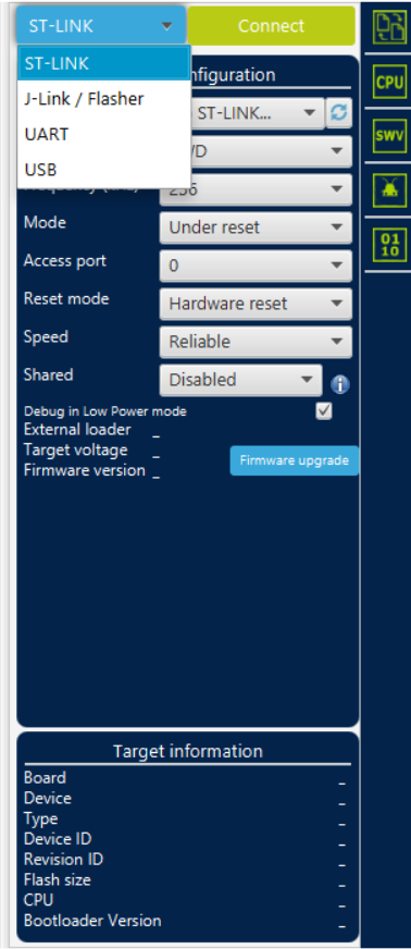
Click Connect. The module should be automatically detected.

Open the Erasing & Programming tab in the left menu.

Click Browse and select the compiled binary file (.bin) exported from Arduino IDE.
Enable both Verify programming and Run after programming checkboxes.
Click Start Programming to upload the firmware.

After programming completes, click OK on the confirmation dialogs.
Firmware Operation
State machine overview
The QSPI eMMC module firmware implements a state machine that manages Red Pitaya power control based on user input and system monitoring. The firmware is written in Arduino C++ and available in the Red Pitaya GitHub repository.
Note
Direct link to firmware will be available soon.
Power states
The firmware manages the following power states:
Power Up
Red Pitaya is booting. After a set timeout, the firmware monitors power and watchdog signals. If signals are not detected, transitions to Power Reset. Otherwise, transitions to Power On.
Power On
Red Pitaya is fully operational. Monitors watchdog and power signals continuously. If the power button is held for one second, transitions to Power Down. If signals are lost, transitions to Power Reset.
Power Down
Initiates graceful shutdown. Sends shutdown signal to Red Pitaya, then waits for a timeout before transitioning to Power Off.
Power Off
Red Pitaya is powered off. Remains in this state until the power button is pressed, then transitions to Power Up.
Power Down Reset
Similar to Power Down but transitions to Power Reset instead of Power Off, allowing automatic restart.
Power Reset
Red Pitaya is powered off temporarily. After a timeout, automatically transitions to Power Up. If this state is reached multiple times consecutively, transitions to Power Fail to prevent boot loops.
Power Fail
Safety state entered after repeated failed boots. Requires manual intervention (power button press) to return to Power Off state.
Note
At any time, pressing and holding the power button forces an immediate power off, overriding the current state.
State diagram

The firmware is designed for easy customization with clear code structure and comprehensive comments. State transitions can be controlled from Red Pitaya using the E3 I2C controller.
E3 I2C Controller
The QSPI eMMC module can be controlled from Red Pitaya via I2C commands. This allows programmatic control of power states and firmware configuration.
E3 I2C controller utility - A command-line tool for sending I2C commands to the module from Red Pitaya.
Hardware Specifications
For detailed hardware specifications, connector pinouts, and schematics, refer to the E3 hardware documentation.
Frequently Asked Questions
Q: Why isn’t my module connecting to the programmer?
Try different USB ports on your computer. Verify cable connections match the diagrams. Test the ST-Link/V2 connection first as it’s the most reliable method.
Q: The firmware uploaded but doesn’t work correctly. What should I check?
Verify all six firmware configuration steps were completed correctly, especially the pin map redefinitions and the build.opt file. Ensure your Red Pitaya board is compatible (Pro Gen 2 models only).
Q: Can I use I2C1 or UART interfaces?
These interfaces are not currently supported as there is no physical connector on the module. The hardware pads exist for future expansion with resistor modifications.
Q: How do I modify the DIO12 differential pair functionality?
Refer to the hardware documentation for resistor configuration instructions to enable I2C1 or UART on the DIO12 pins.
Q: What happens if the Red Pitaya fails to boot?
The firmware automatically detects boot failures and enters Power Reset state. After multiple failed attempts, it enters Power Fail state requiring manual intervention to prevent continuous boot loops.