Logic analyzer extension module
Description
The Logic Analyser extension module extends the available input voltage level range of the eight digital pins (DIO0_P - DIO7_P) used for the logic analyser application and adds overvoltage and overload protection to the digital pins. The extension module is plugged directly into the E1 and E2 extension connectors.
What is in the box?
The expansion module kit includes
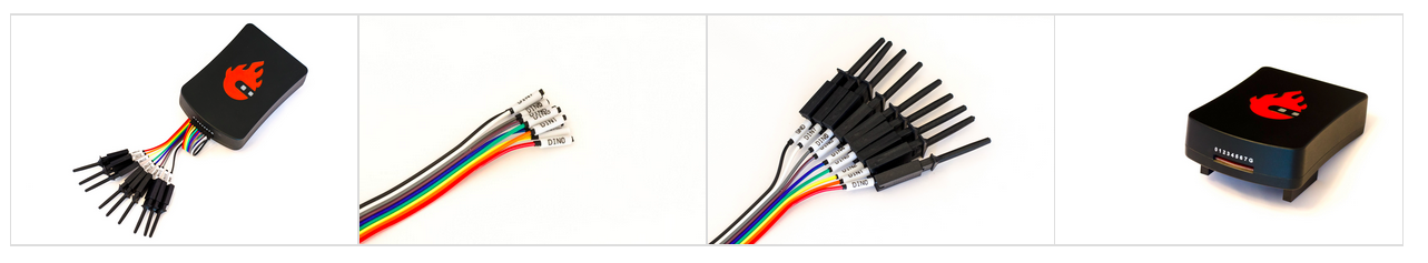
Logic analyser board integrated in an aluminium case
8 channel logic analyser cables
8 detachable probes
Hardware connection
Plug the Logic Analyser extension module connectors directly into the E1 and E2 extension connectors and connect the problem cables. Connect the cables to the desired measurement points.
Check that the GND pin is connected. Leaving the GND pin unconnected may result in unreadable measurements.
Comparison between starndard LA and extension connector
Direct E1 connection |
LA extension module |
|
|---|---|---|
Channels |
8 |
8 |
Sampling rate (max.) |
125 Msps |
125 Msps |
Maximum Input Frequency |
50 MHz |
50 MHz |
Supported bus protocols |
I2C, SPI, UART, CAN |
I2C, SPI, UART, CAN |
Input voltage |
3.3 V |
2.5 … 5.5 V |
DIO overload protection |
N/A |
Integrated |
Level thresholds |
0.8V (low)
2.0V (high)
|
0.8V (low)
2.0V (high)
|
Input impedance |
100 kΩ, 3 pF |
100 kΩ, 3 pF |
Trigger types |
Level, edge, pattern |
Level, edge, pattern |
Memory depth |
1 MS (typical) |
1 MS (typical) |
Sampling interval |
8 ns |
8 ns |
Minimum pulse duration |
10 ns |
10 ns |
Please refer to the Logic analyzer application for more details on the Logic Analyser.
Logic Analyser Q&A
Can I use the Logic Analyser application without the extension connector?
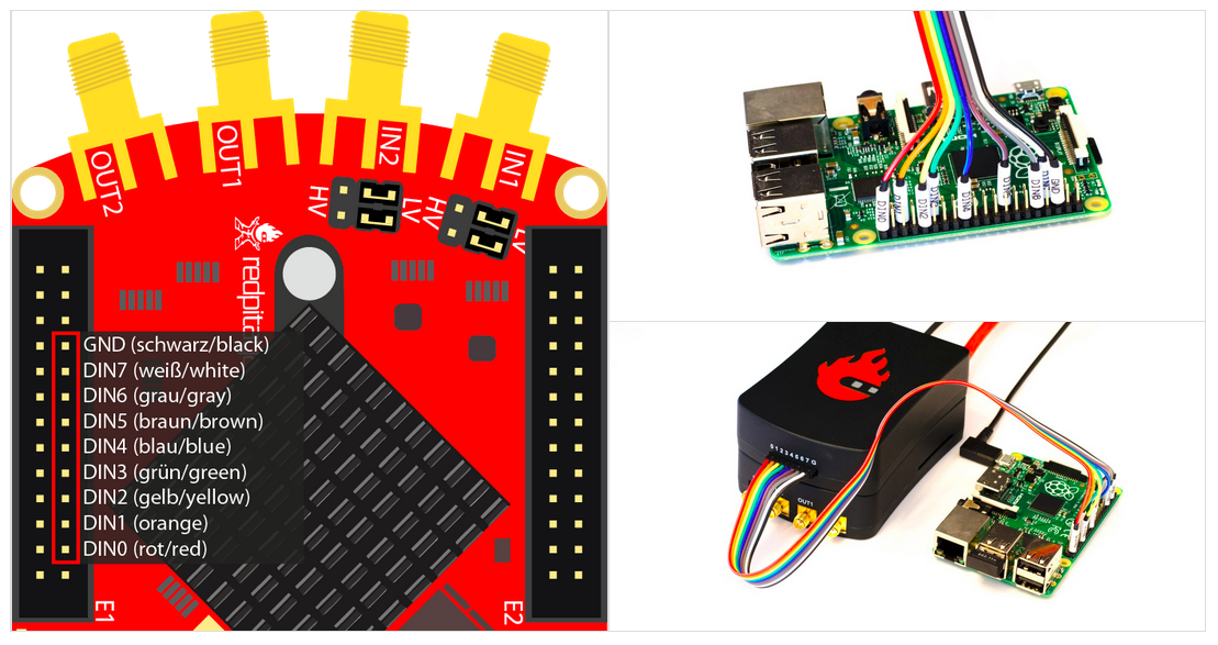
Yes, you can. To use the logic analyser without the extension module, you must be careful when connecting the logic analyser probes to the E1 on the Red Pitaya board, as only 3V3 logic is supported. The pins used for the logic analyser board are shown in the figure below.
Note
On some Red Pitaya board models (SDRlab 122-16, STEMlab 125-14 4-Input, etc.) the DIO8_P pin (labelled GND in the picture above) can be used as a standard GPIO pin. In such case, please use any GND pin on the Red Pitaya board to connect the logic analyzer GND pin.
Which Red Pitaya board models are compatible with the direct LA connection?
Using the GPIO E1 pins of the Red Pitaya board directly will work on any Red Pitaya board model. An example connection is shown in the picture above.