3.2.2.3. Build FPGA image

The following build instructions were tested on Ubuntu 20.04. It is important to install the correct Vivado and SDK versions as the projects and scripts are made for those versions and may return errors during build.

Note

Please note that the FPGA code is located in a seperate repository from the ecosystem on our GitHub page: * Ecosystem: RedPitaya/RedPitaya * FPGA: RedPitaya/RedPitaya-FPGA

Running the “Makefile.x86” will download the necessary files from the RedPitaya/RedPitaya-FPGA repository.

For building the FPGA image for different boards please see the Buildprocess.

3.2.2.3.1. Prerequisites

3.2.2.3.1.1. Libraries used by ModelSim-Altera

Install libraries:

# apt-get install unixodbc unixodbc-dev libncurses-dev libzmq3-dev libxext6 libasound2 libxml2 libx11-6 libxtst6 libedit-dev libxft-dev libxi6 libx11-6:i386 libxau6:i386 libxdmcp6:i386 libxext6:i386 libxft-dev:i386 libxrender-dev:i386 libxt6:i386 libxtst6:i386

3.2.2.3.1.2. Xilinx Vivado 2020.1

Xilinx Vivado is available from Xilinx downloads page:

https://www.xilinx.com/support/download/index.html/content/xilinx/en/downloadNav/vivado-design-tools/archive.html

On officially unsupported versions of Linux, the installer gives you a warning, but Vivado should work fine, for example running it on Ubuntu 20.04 instead of 18.04.

If the installer glitches out anyway, your /etc/os-release file needs to be changed to “fake” the OS version. First, backup the file and then open it as superuser with a text editor such as nano:

$ sudo nano /etc/os-release

and change the VERSION line to “VERSION=”18.04.4 LTS (Bionic Beaver)”” and save the file. The edited file should look something like this:
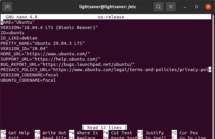
../../../../_images/os_release.png

After that you can either run the Xilinx_Unified_2020.1_0602_1208_Lin64.bin (Linux web-installer) or the xsetup file from the extracted folder (unified installer). After the installation finishes replace the modified file with the one you backed up – failure to do so might cause some problems with other programs.

For more information on Vivado installation, see:

https://redpitaya-knowledge-base.readthedocs.io/en/latest/learn_fpga/3_vivado_env/tutorfpga1.html

3.2.2.3.1.3. Xilinx SDK development environments 2019.1

Xilinx SDK is available from Xilinx downloads page:

https://www.xilinx.com/support/download/index.html/content/xilinx/en/downloadNav/vitis/archive-sdk.html

3.2.2.3.1.4. Device Tree Xilinx

To build fpga requires a repository with a device tree from xilinx. You can prepare it by running the command:

$ make -f Makefile.x86 devicetree

Note

You can upload the file manually:

curl -L https://github.com/Xilinx/device-tree-xlnx/archive/xilinx-v2017.2.tar.gz/ -o device-tree-xlnx-xilinx-v2017.2.tar.gz

and extract the .tar.gz to /[redpitaya path]/tmp/device-tree-xlnx-xilinx-v2017.2

3.2.2.3.2. Directory structure

There are multiple FPGA projects, some with generic functionality, some with specific functionality for an application. Common code for all projects is placed directly into the fpga directory. Common code are mostly reusable modules. Project specific code is placed inside the fpga/prj/name/ directories and is similarly organized as common code.

path

contents

fpga/Makefile

main Makefile, used to run FPGA related tools

fpga/*.tcl

TCL scripts to be run inside FPGA tools

fpga/archive/

archive of XZ compressed FPGA bit files

fpga/doc/

documentation (block diagrams, address space, …)

fpga/brd/

board files Vivado System-Level Design Entry

fpga/ip/

third party IP, for now Zynq block diagrams

fpga/rtl/

Verilog (SystemVerilog) Register-Transfer Level

fpga/sdc/

Synopsys Design Constraints contains Xilinx design constraints

fpga/sim/

simulation scripts

fpga/tbn/

Verilog (SystemVerilog) test bench

fpga/dts/

device tree source include files

fpga/prj/name

project name specific code

fpga/hsi/

Hardware Software Interface contains FSBL (First Stage Boot Loader) and DTS (Design Tree) builds

3.2.2.3.3. FPGA sub-projects

There are multiple FPGA sub-projects they mostly contain incremental changes on the first Red Pitaya release. It is reccommended to use 0.94 release as default project.

prj/name

Description

Application

0.93

This is the original Red Pitaya release including all bugs. For deprecated application backward compatibility only.

0.94

  1. The CDC (clock domain crossing) code on the custom CPU bus
    was removed. Instead CDC for GP0 port already available in
    PS was used. This improves speed and reliability and reduces
    RTL complexity.

  2. A value increment bug in the generator was fixed, this should
    improve generated frequencies near half sampling rate.

  3. XADC custom RTL wrapper was replaced with Xilinx AXI XADC.
    This enables the use of the Linux driver with IIO streaming
    support.

Oscilloscope
Signal generator
Spectrum analyzer
Bode analyzer
LCR meter

stream_app

  1. Streaming ADC and DAC data to/from DDR3 memory buffers.

  2. Streaming GPIO inputs and outputs to/from DDR3 memory buffers.

Streaming manager

classic

  1. A lot of the code was rewritten in SystemVerilog.

  2. Removed GPIO and LED registers from housekeeping, instead the
    GPIO controller inside PL is used. This enables the use of
    Linux kernel features for GPIO (IRQ, SPI, I2C, 1-wire) and
    LED (triggers).

logic

This image is used by the logic analyzer, it is using DMA to
transfer data to main DDR3 RAM. ADC and DAS code is unfinished.

Logic analyzer

axi4lite

Image intended for testing various AXI4 bus implementations.
It contains a Vivado ILA (integrated logic ananlyzer) to
observe and review the performance of the bus implementation.

3.2.2.3.4. Building process

The following table shows which projects are available on which boards.

Build name

STEMlab 125-10
STEMlab 125-14
STEMlab 125-14-Z7020

SIGNALlab 250-12

SDRlab 122-16

STEMlab 125-14 4Ch Z7020

0.94

X

X

X

0.94_250

X

stream_app

X

X

stream_app_250

X

logic

X

logic_250

X

tft

X

axi4lite

X

classic

X

mercury

X

Table of required build flags for FPGA projects per board

Model

Build flag

STEMlab 125-10
STEMlab 125-14

MODEL=Z10 OR
without MODEL flag

STEMlab 125-14-Z7020

MODEL=Z20_14

SDRlab 122-16

MODEL=Z20

SIGNALlab 250-12

MODEL=Z20_250

STEMlab 125-14 4Ch Z7020

MODEL=Z20_125_4CH

On the PC that has Vivado installed run the following commands to properly configure system variables (needs to be done every time you open a new terminal window). Alternatively, you can add the following lines to your .bashrc file using a text editor – this will ensure that they are run at the system startup:

source <path to Xilinx installation directory>/Xilinx/Vivado/2020.1/settings64.sh
source <path to Xilinx installation directory>/Xilinx/SDK/2019.1/settings64.sh

The Xilinx installation directory should be located in /opt directory (or /tools, if you used the default Vivado installation directory). These two commands will setup the $PATH environment variable. It might also be necessary to add SDK bin folder to the $PATH environment variable:

export PATH=<path to Xilinx installation directory>/Xilinx/SDK/2019.1/bin:$PATH

Check if you have Git command line tools installed on your computer:

sudo apt update
sudo apt install git

Create a new directory for the Red Pitaya code. Then download the code by running the following command in the newly created directory:

git clone https://github.com/RedPitaya/RedPitaya.git

The devicetree sources must also be downloaded and extracted by running

make -f Makefile.x86 devicetree

The default mode for building the FPGA is to run a TCL script inside Vivado. Non project mode is used, to avoid the generation of project files, which are too many and difficult to handle. This allows us to only place source files and scripts under version control.

The following scripts perform various tasks:

TCL script

action

red_pitaya_vivado.tcl

creates the bitstream and reports

red_pitaya_vivado_project.tcl

creates a Vivado project for graphical editing

red_pitaya_hsi_fsbl.tcl

creates FSBL executable binary

red_pitaya_hsi_dts.tcl

creates device tree sources

First, change your directory to /<path to Red Pitaya repository>/RedPitaya/fpga. To generate a bit file, reports, device tree and FSBL, run (replace name with project name and model with model flag):

$ make PRJ=name MODEL=model

For example, build v0.94 for STEMlab 125-14:

$ make project PRJ=v0.94 MODEL=Z10

The resulting .bit file is located in /prj/<project name>/out/redpitaya.bit This file must be copied to /opt/redpitaya/fpga on the Red Pitaya itself.

If the script returns the following error:

BD_TCL-109" "ERROR" "This script was generated using Vivado 2020.1 ....

First, find the line containing

set scripts_vivado_version 2020.1

and change 2020.1 to your version. This is a quick and dirty way to get the build working in other versions of Vivado. However, this way could be problematic if some of the IPs used are different in your version.

To update the script properly, open the project GUI(see below), go to menu Reports-> Report IP Status. A new tab opens below the code window. If all IPs are not up-to-date, they need to be updated. Before doing this, the TCL script must still be manually modified to your Vivado version, or the block design will not be created when Vivado starts.

../../../../_images/IPupdate.png

When IPs are up-to-date, go to the tab Tcl console and run command:

write_bd_tcl systemZ10.tcl

Of course, the script may also be named systemZ20.tcl systemZ20_14.tcl, depending on your board.

This generates a new tcl script that replaces the old script in fpga/prj/<project name>/ip

To generate and open a Vivado project using GUI, run:

$ make project PRJ=name MODEL=model

For example, v0.94 project for STEMlab 125-14:

$ make project PRJ=v0.94 MODEL=Z10
../../../../_images/project_make.png

A new, blank project will automatically built and all the necessary files associated with Red Pitaya will be added. You can add/write your Verilog module at the end of red_pitaya_top.sv file (or add a new source by right clicking the Design Sources folder and Add Source):
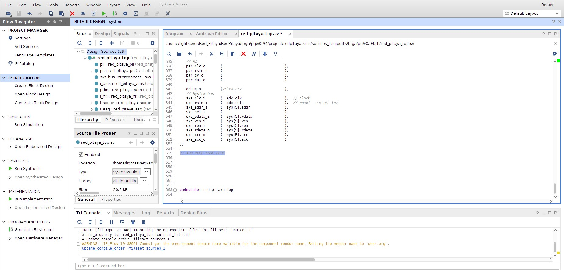
../../../../_images/vivado_project.png

You can connect newly added sources in the Diagram (Block Design) section (If it is not open: Window => Design => double click system). Add them to the design by right click => Add Module in the design window (for more information check the Learn FPGA programming => FPGA lessons section) https://redpitaya-knowledge-base.readthedocs.io/en/latest/learn_fpga/4_lessons/top.html

Before you try to Run Synthesis, Run Implementation or Write Bitstream, you should check Language and Region settings on your Ubuntu computer – make sure you have a Format that uses a dot (“.”) as a decimal separator (United Kingdom or United States will work). Otherwise the Synthesis might fail as some parts of Vivado demand a dot as the decimal separator, which will cause Vivado not to recognize certain parts of the model.

The resulting .bit file is located in fpga/prj/<project name>/project/redpitaya.runs/impl_1/red_pitaya_top.bit This file must be copied to /opt/redpitaya/fpga.

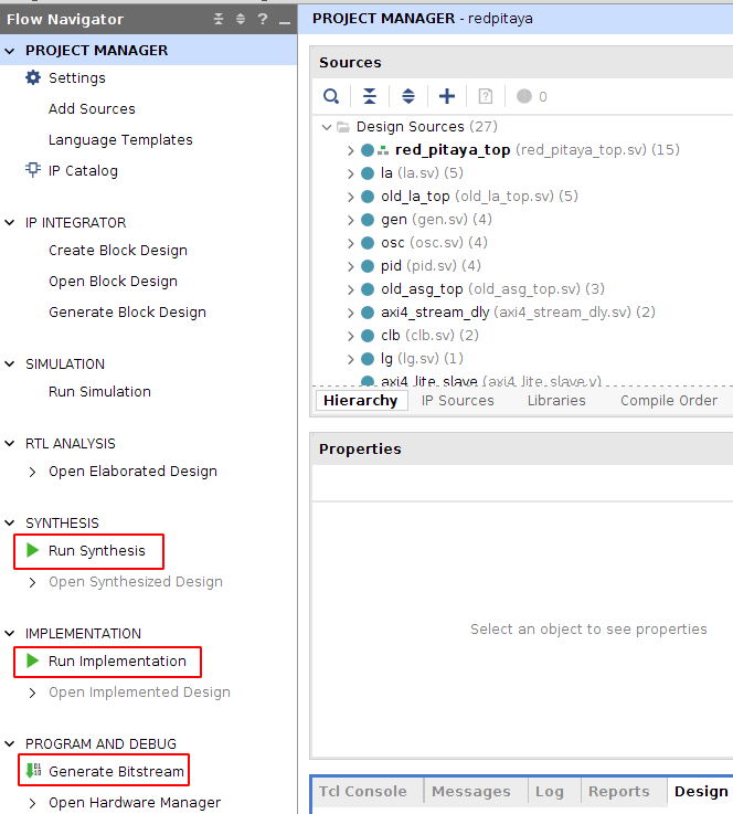
../../../../_images/vivadoGUI.png
  1. Run Synthesis

  2. Run Implementation

  3. Generate Bitstream

The resulting .bit file is located in <Red Pitaya repository>/RedPitaya/fpga/prj/<project name>/project/redpitaya.runs/impl_1/ as red_pitaya_top.bit (the name of the .bit file is the same as the top module of the design)

3.2.2.3.5. Programming via JTAG

These instructions show how to use a JTAG cable to program a Red Pitaya directly from Xilinx Vivado. To do so we use Red Pitaya STEMlab 125-14, Ubuntu 20.04, Vivado 2020.1, Digilent JTAG-HS3 cable with a 14 to 6 pin adapter and Digilent Adept 2 software.

To start, get an appropriate JTAG cable. In these instructions, we use a Digilent JTAG-HS3 cable with a 14 to 6 pin adapter. Digilent JTAG-HS2 may be used as well and might be more appropriate, as it uses a 6 pin connector that can connect directly to Red Pitaya’s JTAG. For a complete list of JTAG cables, supported by Vivado, see Xilinx UG908 - Programming and Debugging, appendix D. https://www.xilinx.com/content/dam/xilinx/support/documentation/sw_manuals/xilinx2021_2/ug908-vivado-programming-debugging.pdf

See if the JTAG cable is detected. In Ubuntu, that is done with:

$ lsusb

JTAG-HS3 is displayed as a FTDI device.

../../../../_images/lsusb.jpg

Now, install Digilent Adept 2 software from https://digilent.com/reference/software/adept/start. You will need both Utilities and Runtime. These are both available as .deb packages. If installing from GUI does not work, they can be installed using:

$ sudo dpkg -i <path to package>

Once these packages are installed, you can check if the driver detects your adapter (only applies to Digilent cables):

$ djtgcfg enum
../../../../_images/driver_check.jpg

Now, open Vivado 2020.1, click Program and Debug -> Open Target -> Auto Connect.
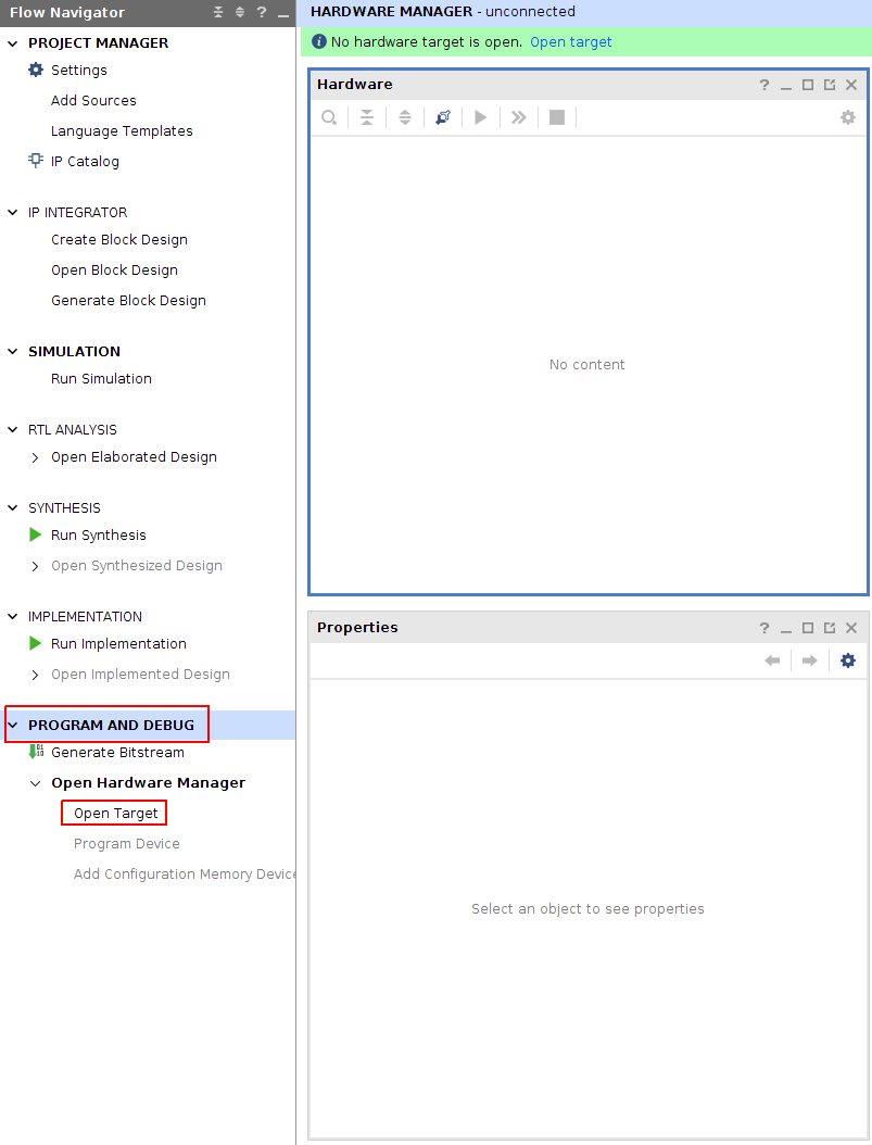
../../../../_images/program_menu.jpg

This will display a Xilinx compatible JTAG cable in the Hardware window, under localhost.

../../../../_images/cable.jpg

Now plug your cable onto Red Pitaya’s JTAG connector. The pins are marked on the bottom side of Red Pitaya’s PCB.
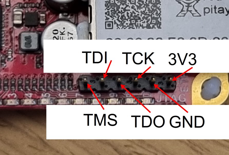
../../../../_images/JTAG_pins.jpg

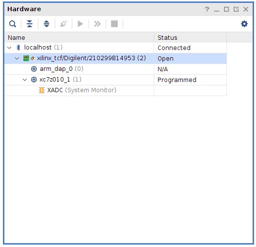
A Xilinx device should now appear in Vivado (on the detected cable). In this case, it’s a xc7z010_1.

../../../../_images/program.jpg

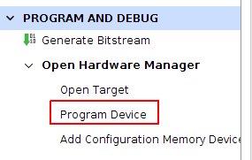
Now, you can click Program Device.

../../../../_images/connected.jpg

A bitfile selector prompt appears and when a valid file is selected, Red Pitaya can be programmed.
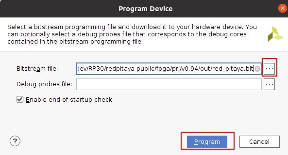
../../../../_images/file_select.jpg

3.2.2.3.6. Simulation

ModelSim as provided for free from Altera is used to run simulations. Scripts expect the default install location. On Ubuntu the install process fails to create an appropriate path to executable files, so this path must be created:

$ ln -s $HOME/intelFPGA/16.1/modelsim_ase/linux $HOME/intelFPGA/16.1/modelsim_ase/linux_rh60
$ sudo apt install libxft2:i386

To run simulation, Vivado tools have to be installed. There is no need to source settings.sh. For now the path to the ModelSim simulator is hard coded into the simulation Makefile.

$ cd fpga/sim

Simulations can be run by running make with the bench file name as target:

$ make top_tb

Some simulations have a waveform window configuration script like top_tb.tcl which will prepare an organized waveform window.

$ make top_tb WAV=1

3.2.2.3.7. Device tree

Device tree is used by Linux to describe features and address space of memory mapped hardware attached to the CPU.

Running make of a project will create a device tree source and some include files in the directory dts:

device tree file

contents

zynq-7000.dtsi

description of peripherals inside PS (processing system)

pl.dtsi

description of AXI attached peripherals inside PL (programmable logic)

system.dts

description of all peripherals, includes the above *.dtsi files

To enable some Linux drivers (Ethernet, XADC, I2C EEPROM, SPI, GPIO and LED) additional configuration files. Generic device tree files can be found in fpga/dts while project specific code is in fpga/prj/name/dts/.

3.2.2.3.8. Signal mapping

3.2.2.3.8.1. XADC inputs

XADC input data can be accessed through the Linux IIO (Industrial IO) driver interface.

E2 con

schematic

ZYNQ p/n

XADC in

IIO filename

measurement target

range

AI0

AIF[PN]0

B19/A20

AD8

in_voltage11_raw

general purpose

7.01V

AI1

AIF[PN]1

C20/B20

AD0

in_voltage9_raw

general purpose

7.01V

AI2

AIF[PN]2

E17/D18

AD1

in_voltage10_raw

general purpose

7.01V

AI3

AIF[PN]3

E18/E19

AD9

in_voltage12_raw

general purpose

7.01V

AIF[PN]4

K9 /L10

AD

in_voltage8_vpvn_raw

5V power supply

12.2V

3.2.2.3.8.1.1. Input range

The default mounting intends for unipolar XADC inputs, which allow for observing only positive signals with a saturation range of 0V ~ 1V. There are additional voltage dividers use to extend this range up to the power supply voltage. It is possible to configure XADC inputs into a bipolar mode with a range of -0.5V ~ +0.5V, but it requires removing R273 and providing a 0.5V ~ 1V common voltage on the E2 connector.

Note

Unfortunately there is a design error, where the XADC input range in unipolar mode was thought to be 0V ~ 0.5V. Consequently the voltage dividers were miss designed for a range of double the supply voltage.

3.2.2.3.8.1.1.1. 5V power supply
                       ----------------0  Vout
          ----------  |  ----------
Vin  0----| 56.0kΩ |-----| 4.99kΩ |----0  GND
          ----------     ----------
\[ \begin{align}\begin{aligned}ratio = \frac{4.99 k\Omega}{56.0 k\Omega +4.99 k\Omega} = 0.0818\\range = \frac{1 V}{ratio} = 12.2 V\end{aligned}\end{align} \]
3.2.2.3.8.1.1.2. General purpose inputs
                       ----------------0  Vout
          ----------  |  ----------
Vin  0----| 30.0kΩ |-----| 4.99kΩ |----0  GND
          ----------     ----------
\[ \begin{align}\begin{aligned}ratio = \frac{4.99 k\Omega}{30.0 k\Omega + 4.99 k\Omega} = 0.143\\range = \frac{1 V}{ratio} = 7.01 V\end{aligned}\end{align} \]

3.2.2.3.8.2. GPIO and LEDs

Handling of GPIO and LED signals depends on wether they are connected to Zynq-7000 PS (MIO) or PL (EMIO or FPGA) block.

MIO pins signals are controlled by the PS block. Each pin has a few multiplexed functions. The multiplexer, slew rate, and pullup resistor enable can be be controlled using software usually with device tree pinctrl code. Xilinx also provides Linux drivers for all PS based peripherals, so all MIO signals can be managed using Linux drivers.

Pins connected to the PL block require FPGA code to function. If the pin signals are wired directly (in the FPGA sources) from PS based EMIO signals to the FPGA pads, then they can be managed using Linux drivers intended for the PS block.

The default pin assignment for GPIO is described in the next table.

FPGA

connector

GPIO

MIO/EMIO index

sysfs index

comments, LED color, dedicated meaning

green, Power Good status

blue, FPGA programming DONE

exp_p_io [7:0]

EMIO[15: 8]

906+54+[15: 8]=[975:968]

exp_n_io [7:0]

EMIO[23:16]

906+54+[23:16]=[983:976]

LED [7:0]

EMIO[ 7: 0]

906+54+[ 7: 0]=[967:960]

yellow

LED `` [8]``

MIO[ 0]

906+   [ 0]   = 906

yellow = CPU heartbeat (user defined)

LED `` [9]``

MIO[ 7]

906+   [ 7]   = 913

red = SD card access (user defined)

D5

E2[ 7]

UART1_TX

MIO[ 8]

906+   [ 8]   = 914

output only

B5

E2[ 8]

UART1_RX

MIO[ 9]

906+   [ 9]   = 915

requires pinctrl changes to be active

E9

E2[ 3]

SPI1_MOSI

MIO[10]

906+   [10]   = 916

requires pinctrl changes to be active

C6

E2[ 4]

SPI1_MISO

MIO[11]

906+   [11]   = 917

requires pinctrl changes to be active

D9

E2[ 5]

SPI1_SCK

MIO[12]

906+   [12]   = 918

requires pinctrl changes to be active

E8

E2[ 6]

SPI1_CS#

MIO[13]

906+   [13]   = 919

requires pinctrl changes to be active

B13

E2[ 9]

I2C0_SCL

MIO[50]

906+   [50]   = 956

requires pinctrl changes to be active

B9

E2[10]

I2C0_SDA

MIO[51]

906+   [51]   = 957

requires pinctrl changes to be active

3.2.2.3.8.3. Linux access to LED

This document is used as reference: http://www.wiki.xilinx.com/Linux+GPIO+Driver

By providing GPIO/LED details in the device tree, it is possible to access LEDs using a dedicated kernel interface.

To show CPU load on LED 9 use:

$ echo heartbeat > /sys/class/leds/led0/trigger

To switch LED 8 ON use:

$ echo 1 > /sys/class/leds/led0/brightness

3.2.2.3.8.4. PS pinctrl for MIO signals

It is possible to modify MIO pin functionality using device tree files during Linux bootup. The listed files should be included in the main device tree.

This files can be modified into device tree overlays, which can be used to modify MIO functionality at runtime.

device tree file

description

spi2gpio.dtsi

E2 connector, SPI1 signals are repurposed as GPIO

i2c2gpio.dtsi

E2 connector, I2C0 signals are repurposed as GPIO

uart2gpio.dtsi

E2 connector, UART1 signals are repurposed as GPIO

miso2gpio.dtsi

E2 connector, SPI1 MISO signal is repurposed as GPIO SPI can then only be used for writing (maybe 3-wire)

3.2.2.3.9. Register map (v0.94)

Red Pitaya HDL design has multiple functions, which are configured by registers. It also uses memory locations to store capture data and generate output signals. All of this are described in this document. Memory location is written in a way that is seen by SW.

The table describes address space partitioning implemented on FPGA via AXI GP0 interface. All registers have offsets aligned to 4 bytes and are 32-bit wide. Granularity is 32-bit, meaning that minimum transfer size is 4 bytes. The organization is little-endian. The memory block is divided into 8 parts. Each part is occupied by individual IP core. Address space of individual application is described in the subsection below. The size of each IP core address space is 4MByte. For additional information and better understanding check other documents (schematics, specifications…).

Start

End

Module Name

CS[0]

0x40000000

0x400FFFFF

Housekeeping

CS[1]

0x40100000

0x401FFFFF

Oscilloscope

CS[2]

0x40200000

0x402FFFFF

Arbitrary signal generator (ASG) 125-14-4ADC: Oscilloscope CHC and CHD

CS[3]

0x40300000

0x403FFFFF

PID controller

CS[4]

0x40400000

0x404FFFFF

Analog mixed signals (AMS)

CS[5]

0x40500000

0x405FFFFF

Daisy chain

CS[6]

0x40600000

0x406FFFFF

FREE

CS[7]

0x40700000

0x407FFFFF

Power test

3.2.2.3.9.1. Red Pitaya Modules

Here are described submodules used in Red Pitaya FPGA logic.

3.2.2.3.9.1.1. Housekeeping

offset

description

bits

R/W

0x0

ID

Reserved

31:4

R

Design ID

3:0

R

0 -prototype

1 -release

0x4

DNA part 1

DNA[31:0]

31:0

R

0x8

DNA part 2

Reserved

31:25

R

DNA[56:32]

24:0

R

0xC

Digital Loopback

Reserved

31:1

R

digital_loop

0

R/W

0x10

Expansion connector direction P

Reserved

31:8

R

Direction for P lines

7:0

R/W

1-out

0-in

0x14

Expansion connector direction N

Reserved

31:8

R

Direction for N lines

7:0

R/W

1-out

0-in

0x18

Expansion connector output P

Reserved

31:8

R

P pins output

7:0

R/W

0x1C

Expansion connector output N

Reserved

31:8

R

N pins output

7:0

R/W

0x20

Expansion connector input P

Reserved

31:8

R

P pins input

7:0

R

0x24

Expansion connector input N

Reserved

31:8

R

N pins input

7:0

R

0x30

LED control

Reserved

31:8

R

LEDs 7-0

7:0

R/W

0x100

FPGA ready

Reserved

31:1

R

Programmable logic is out of reset

0

R

0x1000

External trigger override

Reserved

31:3

R

Trigger output selector 1: DAC trigger, 0: ADC trigger

2

R/W

Override GPIO_N_0 to output ADC or DAC trigger

1

R/W

Enable sending and receiving external trigger through daisy chain connectors 1: enable, 0: disable

0

R/W

3.2.2.3.9.1.2. Oscilloscope

Note

For STEMlab 125-14 4-Input register writes are duplicated for channels A/B and C/D. The output registers are replaced with a mirrored version of the input registers for channels C/D (IN3/IN4).

offset

description

bits

R/W

0x0

Configuration *

Reserved

31:5

R

ACQ delay has passed / (all data was written to buffer)

4

R

Trigger remains armed after ACQ delay passes

3

W

Trigger has arrived stays on (1) until next arm or reset

2

R

Reset write state machine

1

W

Start writing data into memory (ARM trigger).

0

W

0x4

Trigger source *

Selects trigger source for data capture. When trigger delay is ended value goes to 0.

Reserved

31:4

R

Trigger source
1 - trig immediately
2 - ch A threshold positive edge
3 - ch A threshold negative edge
4 - ch B threshold positive edge
5 - ch B threshold negative edge
6 - external trigger positive edge - DIO0_P pin
7 - external trigger negative edge
8 - arbitrary wave generator application positive edge
9 - arbitrary wave generator application negative edge
10- ch C threshold positive edge
11- ch C threshold negative edge
12- ch D threshold positive edge
13- ch D threshold negative edge

3:0

R/W

0x8

Ch A threshold

Reserved

31:14

R

Ch A threshold, makes trigger when ADC value cross this value

13:0

R/W

0xC

Ch B threshold

Reserved

31:14

R

Ch B threshold, makes trigger when ADC value cross this value

13:0

R/W

0x10

Delay after trigger *

Number of decimated data after trigger written into memory

31:0

R/W

0x14

Data decimation *

Decimate input data, uses data average

Reserved

31:17

R

Data decimation: Values 1, 2, 4, 8 are supported for values less than 16. Above 16, averaging of any number of samples is supported.

16:0

R/W

0x18

Write pointer - current

Reserved

31:14

R

Current write pointer

13:0

R

0x1C

Write pointer - trigger

Reserved

31:14

R

Write pointer at time when trigger arrived

13:0

R

0x20

Ch A hysteresis

Reserved

31:14

R

Ch A threshold hysteresis. Value must be outside to enable trigger again.

13:0

R/W

0x24

Ch B hysteresis

Reserved

31:14

R

Ch B threshold hysteresis. Value must be outside to enable trigger again.

13:0

R/W

0x28

Other

Reserved Enable signal average at decimation

31:1 0

R R/W

0x2C

PreTrigger Counter

This unsigned counter holds the number of samples captured between the start of acquire and trigger. The value does not overflow, instead it stops incrementing at 0xffffffff.

31:0

R

0x30

CH A Equalization filter

Reserved

31:18

R

AA Coefficient

17:0

R/W

0x34

CH A Equalization filter

Reserved

31:25

R

BB Coefficient

24:0

R/W

0x38

CH A Equalization filter

Reserved

31:25

R

KK Coefficient

24:0

R/W

0x3C

CH A Equalization filter

Reserved

31:25

R

PP Coefficient

24:0

R/W

0x40

CH B Equalization filter

Reserved

31:18

R

AA Coefficient

17:0

R/W

0x44

CH B Equalization filter

Reserved

31:25

R

BB Coefficient

24:0

R/W

0x48

CH B Equalization filter

Reserved

31:25

R

KK Coefficient

24:0

R/W

0x4C

CH B Equalization filter

Reserved

31:25

R

PP Coefficient

24:0

R/W

0x50

CH A AXI lower address

Starting writing address

31:0

R/W

0x54

CH A AXI upper address

Address where it jumps to lower

31:0

R/W

0x58

CH A AXI delay after trigger

Number of decimated data after trigger written into memory

31:0

R/W

0x5C

CH A AXI enable master

Reserved

31:1

R

Enable AXI master

0

R/W

0x60

CH A AXI write pointer - trigger

Write pointer at time when trigger arrived

31:0

R

0x64

CH A AXI write pointer - current

Current write pointer

31:0

R

0x70

CH B AXI lower address

Starting writing address

31:0

R/W

0x74

CH B AXI upper address

Address where it jumps to lower

31:0

R/W

0x78

CH B AXI delay after trigger

Number of decimated data after trigger written into memory

31:0

R/W

0x7C

CH B AXI enable master

Reserved

31:1

R

Enable AXI master

0

R/W

0x80

CH B AXI write pointer - trigger

Write pointer at time when trigger arrived

31:0

R

0x84

CH B AXI write pointer - current

Current write pointer

31:0

R

0x88

AXI state registers

Reserved

31:21

R

CH B AXI - ACQ delay has passed / (all data was written to buffer)

20

R

CH B AXI - Trigger remains armed / after ACQ delay passes

19

R

CH B AXI - Trigger has arrived stays on (1) until next arm or reset

18

R

Reserved

17

R

CH A AXI - Trigger armed

16

R

Reserved

15:5

R

CH A AXI - ACQ delay has passed / (all data was written to buffer)

4

R

CH A AXI - Trigger remains armed / after ACQ delay passes

3

R

CH A AXI - Trigger has arrived stays on (1) until next arm or reset

2

R

Reserved

1

R

CH A AXI - Trigger armed

0

R

0x90

Trigger debouncer time

Number of ADC clock periods trigger is disabled after activation reset value is decimal 62500 or equivalent to 0.5ms

19:0

R/W

0xA0

Accumulator data sequence length

Reserved

31:14

R

0xA4

Accumulator data offset corection ChA

Reserved

31:14

R

signed offset value

13:0

R/W

0xA8

Accumulator data offset corection ChB

Reserved

31:14

R

signed offset value

13:0

R/W

0x10000 to 0x1FFFC

Memory data (16k samples)

Reserved

31:16

R

Captured data for ch A

15:0

R

0x20000 to 0x2FFFC

Memory data (16k samples)

Reserved

31:16

R

Captured data for ch B

15:0

R

3.2.2.3.9.1.3. Arbitrary Signal Generator (ASG)

Note

Oscilloscope CHC and CHD (125-14 4-Input)

Register writes synchronised between channels A/B and C/D on 4 input board 125-14 4-Input The output registers are replaced with a mirrored version of the input registers for channels C/D (IN3/IN4).

offset

description

bits

R/W

0x0

Configuration

Reserved

31:25

R

ch B external gated repetitions

24

R/W

ch B set output to 0

23

R/W

ch B SM reset

22

R/W

Reserved

21

R/W

ch B SM wrap pointer (if disabled starts at address0 )

20

R/W

ch B trigger selector: (don’t change when SM is
active)
1-trig immediately
2-external trigger positive edge - DIO0_P pin
3-external trigger negative edge

19:16

R/W

Reserved

15:9

R

ch A external gated bursts

8

R/W

ch A set output to 0

7

R/W

ch A SM reset

6

R/W

Reserved

5

R/W

ch A SM wrap pointer (if disabled starts at address 0)

4

R/W

ch A trigger selector: (don’t change when SM is
active)
1-trig immediately
2-external trigger positive edge - DIO0_P pin
3-external trigger negative edge

3:0

R/W

0x4

Ch A amplitude scale and offset

out = (data*scale)/0x2000 + offset

Reserved

31:30

R

Amplitude offset

29:16

R/W

Reserved

15:14

R

Amplitude scale. 0x2000 == multiply by 1. Unsigned

13:0

R/W

0x8

Ch A counter wrap

Reserved

31:30

R

Value where counter wraps around. Depends on SM wrap setting. If it is 1 new value is get by wrap, if value is 0 counter goes to offset value. 16 bits for decimals.

29:0

R/W

0xC

Ch A start offset

Reserved

31:30

R

Counter start offset. Start offset when trigger arrives. 16 bits for decimals.

29:0

R/W

0x10

Ch A counter step

Reserved

31:30

R

Counter step. 16 bits for decimals.

29:0

R/W

0x14

Ch A counter step- lower bits

Counter step read

31:0

R

0x18

Ch A number of read cycles in one burst

Reserved

31:16

R

Number of repeats of table readout. 0=infinite

15:0

R/W

0x1C

Ch A number of burst repetitions

Reserved

31:16

R

Number of repetitions. 0=disabled 0xffff=infinite

15:0

R/W

0x20

Ch A delay between burst repetitions

Delay between repetitions. Granularity=1us

31:0

R/W

0x24

Ch B amplitude scale and offset

out = (data*scale)/0x2000 + offset

Reserved

31:30

R

Amplitude offset

29:16

R/W

Reserved

15:14

R

Amplitude scale. 0x2000 == multiply by 1. Unsigned

13:0

R/W

0x28

Ch B counter wrap

Reserved

31:30

R

Value where counter wraps around. Depends on SM wrap setting. If it is 1 new value is get by wrap, if value is 0 counter goes to offset value. 16 bits for decimals.

29:0

R/W

0x2C

Ch B start offset

Reserved

31:30

R

Counter start offset. Start offset when trigger arrives. 16 bits for decimals.

29:0

R/W

0x30

Ch B counter step

Reserved

31:30

R

Counter step. 16 bits for decimals.

29:0

R/W

0x34

Ch B counter step- lower bits

Counter step read

31:0

R

0x38

Ch B number of read cycles in one burst

Reserved

31:16

R

Number of repeats of table readout. 0=infinite

15:0

R/W

0x3C

Ch B number of burst repetitions

Reserved

31:16

R

Number of repetitions. 0=disabled 0xffff=infinite

15:0

R/W

0x40

Ch B delay between burst repetitions

Delay between repetitions. Granularity=1us

31:0

R/W

0x44

Ch A value of last sample in burst

Reserved

31:14

R

Last value of burst

13:0

R/W

0x48

Ch B value of last sample in burst

Reserved

31:14

R

Last value of burst

13:0

R/W

0x4C

Ch A counter step- lower bits

Counter step write

31:0

W

0x50

Ch B counter step- lower bits

Counter step write

31:0

W

0x54

External trigger debouncer

Number of ADC clock periods trigger is disabled after activation. Default value is decimal 62500 or equivalent to 0.5ms

19:0

R/W

0x60

Ch A buffer current read pointer

Reserved

31:16

R

Read pointer

15:2

R/W

Reserved

1:0

R

0x64

Ch B buffer current read pointer

Reserved

31:16

R

Read pointer

15:2

R/W

Reserved

1:0

R

0x68

**Ch A initial value of generator **

Reserved

31:14

R

First value

13:0

R/W

0x6C

**Ch B initial value of generator **

Reserved

31:14

R

First value

13:0

R/W

0x10000 to 0x1FFFC

Ch A memory data (16k samples)

Reserved

31:14

R

ch A data

13:0

R/W

0x20000 to 0x2FFFC

Ch B memory data (16k samples)

Reserved

31:14

R

ch B data

13:0

R/W

3.2.2.3.9.1.4. PID Controller

offset

description

bits

R/W

0x0

Configuration

Reserved

31:4

R

PID22 integrator reset

3

R/W

PID21 integrator reset

2

R/W

PID12 integrator reset

1

R/W

PID11 integrator reset

0

R/W

0x10

PID11 set point

Reserved

31:14

R

PID11 set point

13:0

R/W

0x14

PID11 proportional coefficient

Reserved

31:14

R

PID11 Kp

13:0

R/W

0x18

PID11 integral coefficient

Reserved

31:14

R

PID11 Ki

13:0

R/W

0x1C

PID11 derivative coefficient

Reserved

31:14

R

PID11 Kd

13:0

R/W

0x20

PID12 set point

Reserved

31:14

R

PID12 set point

13:0

R/W

0x24

PID12 proportional coefficient

Reserved

31:14

R

PID12 Kp

13:0

R/W

0x28

PID12 integral coefficient

Reserved

31:14

R

PID12 Ki

13:0

R/W

0x2C

PID12 derivative coefficient

Reserved

31:14

R

PID12 Kd

13:0

R/W

0x30

PID21 set point

Reserved

31:14

R

PID21 set point

13:0

R/W

0x34

PID21 proportional coefficient

Reserved

31:14

R

PID21 Kp

13:0

R/W

0x38

PID21 integral coefficient

Reserved

31:14

R

PID21 Ki

13:0

R/W

0x3C

PID21 derivative coefficient

Reserved

31:14

R

PID21 Kd

13:0

R/W

0x40

PID22 set point

Reserved

31:14

R

PID22 set point

13:0

R/W

0x44

PID22 proportional coefficient

Reserved

31:14

R

PID22 Kp

13:0

R/W

0x48

PID22 integral coefficient

Reserved

31:14

R

PID22 Ki

13:0

R/W

0x4C

PID22 derivative coefficient

Reserved

31:14

R

PID22 Kd

13:0

R/W

offset

description

bits

R/W

0x0

XADC AIF0 (disabled)

Reserved

31:12

R

AIF0 value

11:0

R

0x4

XADC AIF1 (disabled)

Reserved

31:12

R

AIF1 value

11:0

R

0x8

XADC AIF2 (disabled)

Reserved

31:12

R

AIF2 value

11:0

R

0xC

XADC AIF3 (disabled)

Reserved

31:12

R

AIF3 value

11:0

R

0x10

XADC AIF4 (disabled)

Reserved

31:12

R

AIF4 value (5V power supply)

11:0

R

0x20

PWM DAC0

Reserved

31:24

R

PWM value (100% == 255)

23:16

R/W

Bit select for PWM repetition which have value PWM+1

15:0

R/W

0x24

PWM DAC1

Reserved

31:24

R

PWM value (100% == 255)

23:16

R/W

Bit select for PWM repetition which have value PWM+1

15:0

R/W

0x28

PWM DAC2

Reserved

31:24

R

PWM value (100% == 255)

23:16

R/W

Bit select for PWM repetition which have value PWM+1

15:0

R/W

0x2C

PWM DAC3

Reserved

31:24

R

PWM value (100% == 255)

23:16

R/W

Bit select for PWM repetition which have value PWM+1

15:0

R/W

3.2.2.3.9.1.5. Daisy Chain

offset

description

bits

R/W

0x0

Control

Reserved

31:2

R

RX enable

1

R/W

TX enable

0

R/W

0x4

Transmitter data selector

Custom data

31:1

R/W

Reserved

15:8

R

Data source
0 - data is 0
1 - user data (from logic)
2 - custom data (from this register)
3 - training data (0x00FF)
4 - transmit received data (loop back)
5 - random data (for testing)

3:0

R/W

0x8

Receiver training

Reserved

31:2

R

Training successful

1

R

Enable training

0

R/W

0xC

Received data

Received data which is different than 0

31:1

R

Received raw data

15:0

R

0x10

Testing control

Reserved

31:1

R

Reset testing counters (error & data)

0

R/W

0x14

Testing error counter

Error increases if received data is not the same as transmitted testing data

31:0

R

0x18

Testing data counter

Counter increases when value different as 0 is received

31:0

R

3.2.2.3.9.1.6. Power Test

offset

description

bits

R/W

0x0

Control

Reserved

31:1

R

Enable module

0

R/W

3.2.2.3.10. Register map (stream_app)

Start

End

Module Name

CS[0]

0x40000000

0x400FFFFF

ADC streaming (IN)

CS[1]

0x40100000

0x401FFFFF

DAC streaming (OUT)

CS[2]

0x40200000

0x402FFFFF

GPIO streaming (IN/OUT)

offset

description

bits

R/W

0x0

Event status register

Reserved

31:4

R

Trigger event

3

R/W

Stop event

2

R/W

Start event

1

R/W

Reset event

0

R/W

0x4

Event select register

Reserved

31:5

R

Logic analyser event

4

W

Scope CH2 event

3

W

Scope CH1 event

2

W

Signal generator CH2 event

1

W

Signal generator CH1 event

0

W

0x8

Trigger mask

Reserved

31:6

R

External board trigger

5

W

Logic analyser trigger

4

W

Scope CH2 trigger

3

W

Scope CH1 trigger

2

W

Signal generator CH2 trigger

1

W

Signal generator CH1 trigger

0

W

0x10

Trigger pre samples

Number of pre-trigger samples

31:0

W

0x14

Trigger post samples

Number of post-trigger samples

31:0

W

0x18

Trigger pre counter

Actual count of pre-trigger samples

31:0

R

0x1C

Trigger post counter

Actual count of post-trigger samples

31:0

R

0x20

Trigger low level

Reserved

31:16

R

Low trigger level

15:0

W

0x24

Trigger high level

Reserved

31:16

R

High trigger level

15:0

W

0x28

Trigger edge

Reserved

31:1

R

Trigger edge

0

W

0 - Rising edge

1 - Falling edge

0x30

Decimation factor

Reserved

31:17

R

Decimation factor

16:0

W

0x34

Decimation right shift

Reserved

31:4

R

Decimation right shift

3:0

W

0x38

Averaging enable

Reserved

31:1

R

Averaging enable

0

W

0 - Disabled

1 - Enabled

0x3C

Filter bypass

Reserved

31:1

R

Filter bypass

0

W

0 - Disabled

1 - Enabled

0x40

Digital loopback

Reserved

31:21

R

Use ramp signal ADC CH4

20

R/W

Reserved

19:17

R

Use ramp signal ADC CH3

16

R/W

Reserved

15:13

R

Use ramp signal ADC CH2

12

R/W

Reserved

11:9

R

Use ramp signal ADC CH1

8

R/W

ADC CH2

7:6

R

Loopback DAC CH2

5

R/W

Loopback GPIO N

4

R/W

ADC CH1

3:2

R

Loopback DAC CH1

1

R/W

Loopback GPIO P

0

R/W

0x44

8 bit resolution enable

Reserved

31:1

R

8 bit enable

0

W

0 - Disabled - use 16 bit resolution

1 - Enabled

0x50

DMA control register

Reserved

31:10

R

Streaming DMA mode

9

W

Normal DMA mode

8

W

Reserved

7:5

R

Reset buffers and flags

4

W

Buffer 2 acknowledge

3

W

Buffer 1 acknowledge

2

W

Interrupt acknowledge

1

W

Start DMA

0

W

0x54

DMA status register

Reserved

31:4

R

Buffer 2 overflow

3

R

Buffer 1 overflow

2

R

Buffer 2 full

1

R

Buffer 1 full

0

R

0x58

DMA buffer size

DMA buffer size

31:0

R/W

0x5C

Number of lost samples - buffer 1

Counter of lost samples - buffer 1

31:0

R

0x60

Number of lost samples - buffer 2

Counter of lost samples - buffer 2

31:0

R

0x64

DMA destination address - buffer 1, CH1

DMA destination address - buffer 1

31:0

R/W

0x68

DMA destination address - buffer 2, CH1

DMA destination address - buffer 2

31:0

R/W

0x6C

DMA destination address - buffer 1, CH2

DMA destination address - buffer 1

31:0

R/W

0x70

DMA destination address - buffer 2, CH2

DMA destination address - buffer 2

31:0

R/W

0x74

Calibration offset value CH1

Reserved

31:16

R

Calibration offset value CH1

15:0

R/W

0x78

Calibration gain value CH1

Reserved

31:16

R

Calibration gain value CH1

15:0

R/W

0x7C

Calibration offset value CH2

Reserved

31:16

R

Calibration offset value CH2

15:0

R/W

0x80

Calibration gain value CH2

Reserved

31:16

R

Calibration gain value CH2

15:0

R/W

0x9C

Number of lost samples - buffer 1 CH2

Counter of lost samples - buffer 1

31:0

R

0xA0

Number of lost samples - buffer 2 CH2

Counter of lost samples - buffer 2

31:0

R

0xA4

Diagnostics - current write pointer CH1

Write pointer

31:0

R

0xA8

Diagnostics - current write pointer CH2

Write pointer

31:0

R

0xC0

Filter coefficient AA - CH1

Reserved

31:18

R

AA coefficient

17:0

W

0xC4

Filter coefficient BB - CH1

Reserved

31:24

R

BB coefficient

23:0

W

0xC8

Filter coefficient KK - CH1

Reserved

31:24

R

KK coefficient

23:0

W

0xCC

Filter coefficient PP - CH1

Reserved

31:0

R

PP coefficient

23:0

W

0xD0

Filter coefficient AA - CH2

Reserved

31:18

R

AA coefficient

17:0

W

0xD4

Filter coefficient BB - CH2

Reserved

31:24

R

BB coefficient

23:0

W

0xD8

Filter coefficient KK - CH2

Reserved

31:24

R

KK coefficient

23:0

W

0xDC

Filter coefficient PP - CH2

Reserved

31:0

R

PP coefficient

23:0

W

0x100

Board status

Reserved

31:2

R

Board mode

1

R

1: slave; 0: master

Shows presence of clock on SATA connector in

Bit 0 must be set for this value to be valid

ADC clock is present, PLL locked

0

R

offset

description

bits

R/W

0x0

Configuration

Reserved

31:25

R

ch B set output to 0

23

R/W

Reserved

21

R/W

ch B trigger selector: (don’t change when SM is
active)
1-trig immediately
2-external trigger positive edge - DIO0_P pin
3-external trigger negative edge

19:16

R/W

Reserved

15:9

R

ch A set output to 0

7

R/W

Reserved

5

R/W

ch A trigger selector: (don’t change when SM is
active)
1-trig immediately
2-external trigger positive edge - DIO0_P pin
3-external trigger negative edge

3:0

R/W

0x4

Ch A amplitude scale and offset

out = (data*scale)/0x2000 + offset

Reserved

31:30

R

Amplitude offset

29:16

R/W

Reserved

15:14

R

Amplitude scale. 0x2000 == multiply by 1. Unsigned

13:0

R/W

0x8

Ch A counter step

Counter step. 16 bits for decimals.

31:0

R/W

0xC

Ch A buffer current read pointer

Read pointer

31:0

R

0x10

Ch B amplitude scale and offset

out = (data*scale)/0x2000 + offset

Reserved

31:30

R

Amplitude offset

29:16

R/W

Reserved

15:14

R

Amplitude scale. 0x2000 == multiply by 1. Unsigned

13:0

R/W

0x14

Ch B counter step

Counter step. 16 bits for decimals.

31:0

R/W

0x18

Ch B buffer current read pointer

Read pointer

31:0

R

0x1C

Event status register

Reserved

31:4

R

Trigger event

3

R/W

Stop event

2

R/W

Start event

1

R/W

Reset event

0

R/W

0x20

Event select register

Reserved

31:5

R

Logic analyser event

4

W

Scope CHB event

3

W

Scope CHA event

2

W

Signal generator CHB event

1

W

Signal generator CHA event

0

W

0x24

Trigger mask

Reserved

31:5

R

Logic analyser trigger

4

W

Scope CH B trigger

3

W

Scope CH A trigger

2

W

Signal generator CH B trigger

1

W

Signal generator CH A trigger

0

W

0x28

DMA control register

Reserved

31:14

R

Buffer 2 ready CHB

15

W

Buffer 1 ready CHB

14

W

Streaming DMA mode CHB

13

W

Normal DMA mode CHB

12

W

Reserved

11:10

R

Reset buffers and flags CHB

9

W

Start DMA CHB

8

W

Buffer 2 ready CHA

7

W

Buffer 1 ready CHA

6

W

Streaming DMA mode CHA

5

W

Normal DMA mode CHA

4

W

Reserved

3:2

R

Reset buffers and flags CHA

1

W

Start DMA CHA

0

W

0x2C

DMA status register

Reserved

31:23

R

Sending DMA REQ buffer 2 state

22

R

Sending DMA REQ buffer 1 state

21

R

Reset state

20

R

End state buffer 2

19

R

Read state buffer 2

18

R

End state buffer 1

17

R

Read state buffer 1

16

R

Reserved

15:7

R

Sending DMA REQ buffer 2 state

6

R

Sending DMA REQ buffer 1 state

5

R

Reset state

4

R

End state buffer 2

3

R

Read state buffer 2

2

R

End state buffer 1

1

R

Read state buffer 1

0

R

0x34

DMA buffer size

DMA buffer size

31:0

R/W

0x38

DMA buffer 1 address CH A

DMA buffer address

31:0

R/W

0x3C

DMA buffer 2 address CH A

DMA buffer address

31:0

R/W

0x40

DMA buffer 1 address CH B

DMA buffer address

31:0

R/W

0x44

DMA buffer 2 address CH B

DMA buffer address

31:0

R/W

0x48

Error counter expected step CHA

Reserved

31:16

R

Counter step (due to decimation)

15:0

W

0x4C

Error counter expected step CHB

Reserved

31:16

R

Counter step (due to decimation)

15:0

W

0x50

Reset error counters

Reserved

31:1

R

Counter step (due to decimation)

0

W

0x54

Error counter CHA

Number of errors

31:0

R

0x58

Error counter CHB

Number of errors

31:0

R

0x5C

Digital loopback

Reserved

31:8

R

DAC CH2

7:5

R

Loopback DAC CH2 - output raw data

4

W

DAC CH1

3:1

R

Loopback DAC CH1 - output raw data

0

W

0x60

Bitshift right CHA

Shift raw data from RAM right

31: 5

R

Shift in number of bits

4:0

R/W

0x64

Bitshift right CHB

Shift raw data from RAM right

31: 5

R

Shift in number of bits

4:0

R/W

RLE output encoding: The written number of samples equals to (desired number - 1), max 0xFF (8 bits available) Not less than 1 - limited to one change per 2 clock cycles A 32 bit chunk of data is structured like this: [ 7: 0] RLE decode number for all bits [15: 0] Reserved [23:16] GPIO_x_N bits [31:24] GPIO_x_P bits

offset

description

bits

R/W

0x0

GPIO Status reg

Reserved

31:4

R

Acquire stopped

3

R

Acquire start

2

R

Trigger received

1

R

Reserved

0

0x4

Acquire mode

Reserved

31:2

R

Automatic mode

1

R/W

Continous mode

0

R/W

0x10

Number of pre-trigger samples

Number of samples

31:0

R/W

0x14

Number of post-trigger samples

Number of samples

31:0

R/W

0x18

Current pre-trigger samples

Number of samples

31:0

R/W

0x1C

Current post-trigger samples

Number of samples

31:0

R/W

0x20

Timestamp of acquire - low bits

Timestamp[31:0]

31:0

R

0x24

Timestamp of acquire - high bits

Timestamp[63:32]

31:0

R

0x28

Timestamp of trigger - low bits

Timestamp[31:0]

31:0

R

0x2C

Timestamp of trigger - high bits

Timestamp[63:32]

31:0

R

0x30

Timestamp of stop - low bits

Timestamp[31:0]

31:0

R

0x34

Timestamp of stop - high bits

Timestamp[63:32]

31:0

R

0x40

Trigger - comparator mask

Reserved

31:8

R

Comparator mask

7:0

R/W

0x44

Trigger - comparator value

Reserved

31:8

R

Comparator value

7:0

R/W

0x48

Trigger - positive edge

Reserved

31:8

R

Negative edge

7:0

R/W

0x4C

**Trigger - negative edge **

Reserved

31:8

R

Negative edge

7:0

R/W

0x50

Decimation factor

Decimation factor

31:0

R/W

0x54

RLE enable

Reserved

31:1

R

RLE enable

0

R/W

0x58

Current counter

Counter

31:0

R

0x5C

Last packet

Counter

31:0

R

0x60

Input polarity

Reserved

31:8

R

Input polarity

7:0

R/W

0x70

GPIO direction - p

Reserved

31:8

R

GPIO direction

7:0

R/W

0x74

GPIO direction - n

Reserved

31:8

R

GPIO direction

7:0

R/W

0x80

Event select register

Reserved

31:5

R

Logic analyser event

4

W

Scope CHB event

3

W

Scope CHA event

2

W

Signal generator CHB event

1

W

Signal generator CHA event

0

W

0x84

Trigger mask

Reserved

31:6

R

External trigger

5

W

Logic analyser trigger

4

W

Scope CH B trigger

3

W

Scope CH A trigger

2

W

Signal generator CH B trigger

1

W

Signal generator CH A trigger

0

W

0x88

Event status register

Reserved

31:4

R

Trigger event

3

R/W

Stop event

2

R/W

Start event

1

R/W

Reset event

0

R/W

0x8C

DMA control register - IN

Reserved

31:10

R

Streaming DMA mode

9

W

Normal DMA mode

8

W

Reserved

7:5

R

Reset buffers and flags

4

W

Buffer 2 acknowledge

3

W

Buffer 1 acknowledge

2

W

Interrupt acknowledge

1

W

Start DMA

0

W

0x90

DMA control register - OUT

Reserved

31:8

R

Buffer 2 ready OUT

7

W

Buffer 1 ready OUT

6

W

Streaming DMA mode OUT

5

W

Normal DMA mode OUT

4

W

Reserved

3:2

R

Reset buffers and flags OUT

1

W

Start DMA OUT

0

W

0x94

DMA status register IN

Reserved

31:4

R

Buffer 2 overflow

3

R

Buffer 1 overflow

2

R

Buffer 2 full

1

R

Buffer 1 full

0

R

0x98

DMA status register OUT

Reserved

31:5

R

Reset state

4

R

Read state buffer 2

3

R

End state buffer 2

2

R

Read state buffer 1

1

R

End state buffer 1

0

R

0x9C

DMA buffer size

DMA buffer size

31:0

R/W

0xA0

DMA buffer 1 address IN

DMA buffer address

31:0

R/W

0xA4

DMA buffer 1 address OUT

DMA buffer address

31:0

R/W

0xA8

DMA buffer 2 address IN

DMA buffer address

31:0

R/W

0xAC

DMA buffer 2 address OUT

DMA buffer address

31:0

R/W

0xB0

Buffer 1 missed sample counter IN

Number of missed samples

31:0

R/W

0xB4

Buffer 2 missed sample counter IN

Number of missed samples

31:0

R/W

0xB8

GPIO IN - write pointer

Write pointer

31:0

R/W

0xBC

GPIO OUT - read pointer

Read pointer

31:0

R/W

0xC0

GPIO OUT - step of read pointer

Step

31:0

R/W