3.2.1.2. Setting up the serial console
The debug console can be used to follow the boot process:
FSBL (if debug mode is enabled)
The serial console can also be used to see the output of other bare metal applications, for example, the memory test.
U-Boot
During the boot process, U-Boot will show status and debug information.
After FSBL starts U-Boot, there is a 3-second delay before U-Boot starts the Linux kernel. If during this time a key is pressed, U-boot will stop the boot process and give the user access to its shell.
Linux console
During the boot process, Linux will show status and debug information.
When
systemdreachesmulti-user.targeta login prompt will appear.User name:
rootPassword:root
3.2.1.2.1. Hardware setup
Note
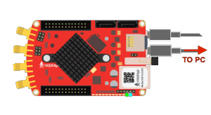
For STEMlab 125-14, you will need an additional USB to micro USB cable. For STEMlab 125-10, you will need a serial to USB adapter (the pins must first be soldered).
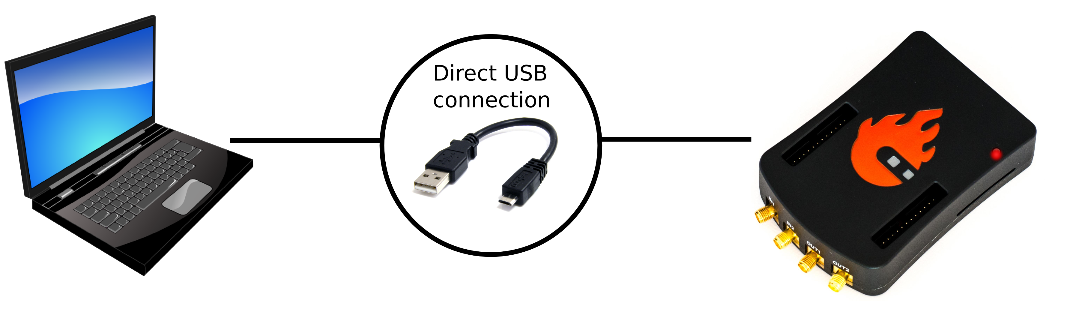
Connect your Red Pitaya and PC with a micro USB B to USB A cable and follow the instructions for your OS.
3.2.1.2.1.1. Windows
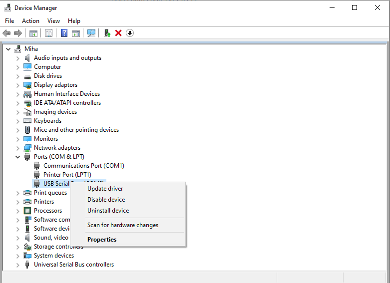
Download and install the FTDI driver on your PC. After installation, a new COM port will appear in the Device Manager, which you can use in Hyperterminal or another terminal utility to connect to Red Pitaya. Connect your Red Pitaya to the micro USB port on the board. In your terminal utility, fill in the serial port name and set the speed to 115200.
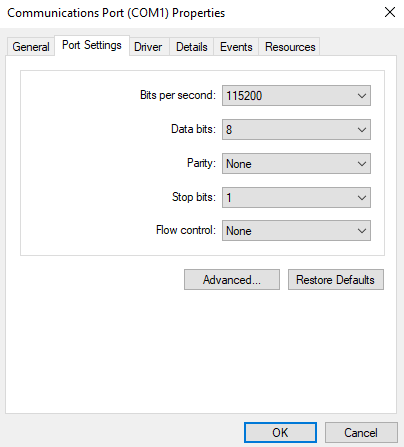
To adjust the connection settings for serial communication, right-click on the COM port and select Properties.
Boot reference must be done through Minicom or a similar serial console application.
One of the options is to install the WSL (Windows Subsystem for Linux) and then install the relevant tools for the console interface. Here are the relevant links:
Afterwards, follow the instructions in the Linux section.
3.2.1.2.1.2. Linux
There is broad support for USB to serial converters in the Linux kernel, so in most cases, the converter will be detected soon after connecting it.
You can see the driver output in the kernel log using dmesg:
$ dmesg
...
[95074.784075] usb 1-2.4.3: new full-speed USB device number 20 using ehci-pci
[95074.885386] usb 1-2.4.3: New USB device found, idVendor=0403, idProduct=6015
[95074.885399] usb 1-2.4.3: New USB device strings: Mfr=1, Product=2, SerialNumber=3
[95074.885406] usb 1-2.4.3: Product: FT231X USB UART
[95074.885411] usb 1-2.4.3: Manufacturer: FTDI
[95074.885416] usb 1-2.4.3: SerialNumber: DN003P0Q
[95074.890105] ftdi_sio 1-2.4.3:1.0: FTDI USB Serial Device converter detected
[95074.890228] usb 1-2.4.3: Detected FT-X
[95074.891157] usb 1-2.4.3: FTDI USB Serial Device converter now attached to ttyUSB0
The first board connected to your PC will create a device named /dev/ttyUSB0. If N USB or serial devices are connected, they will appear as ‘’/dev/ttyUSBn``, where n is {0, 1, …, N-1}. To access these devices, programs should be run with sudo.
Boot reference must be done through Minicom or a similar serial console application.
3.2.1.2.1.2.1. minicom
Minicom is a text-based modem control and terminal emulation program. It is commonly used for setting up a remote serial console.
To configure minicom use the -s option.
sudo minicom -s
A configuration menu will open.
+-----[configuration]------+
| Filenames and paths      |
| File transfer protocols  |
| Serial port setup        |
| Modem and dialing        |
| Screen and keyboard      |
| Save setup as dfl        |
| Save setup as..          |
| Exit                     |
| Exit from Minicom        |
+--------------------------+
Go to Serial Port Setup, press Enter, and set up the next options:
Serial Device:
/dev/ttyUSB0(device index0or a higher number)Bps/Par/Bits:
115200 8N1(baud rate, byte length, parity, and stop bits)Hardware/Software Flow Control: No (flow control should be disabled)
+-----------------------------------------------------------------------+
| A -    Serial Device      : /dev/ttyUSB0                              |
| B - Lockfile Location     : /var/lock                                 |
| C -   Callin Program      :                                           |
| D -  Callout Program      :                                           |
| E -    Bps/Par/Bits       : 115200 8N1                                |
| F - Hardware Flow Control : No                                        |
| G - Software Flow Control : No                                        |
|                                                                       |
|    Change which setting?                                              |
+-----------------------------------------------------------------------+
Minicom requires some special Control+A key sequences to operate.
Please see the minicom manual for details.
After you have configured the details, exit the settings. Minicom should connect you to Red Pitaya, and you should be asked to log in after pressing Enter (see “3.2.1.2” at the top of the page” for the username and password). Should that not happen, leave the Minicom open and unplug Red Pitaya from power; after plugging it back in, you should see the boot sequence for Red Pitaya.
3.2.1.2.1.2.2. screen
GNU screen is, in general, a terminal multiplexer. It also supports connecting to a serial console and provides syntax to configure the serial connection’s baud rate, byte length, parity, and flow control.
Compared to Minicom, it provides better fonts and support for terminal window resizing.
$ sudo screen /dev/ttyUSB1 115200 cs8
Similar to Minicom, screen requires some special Control+A key sequences to operate.
Please see the screen manual for details.
3.2.1.2.2. Reference boot sequence
You can compare these reference boot sequences against yours.
3.2.1.2.2.1. U-Boot
U-Boot 2016.01 (Nov 16 2016 - 12:23:28 +0100), Build: jenkins-redpitaya-master-156

Model: Red Pitaya Board
Board: Xilinx Zynq
I2C:   ready
DRAM:  ECC disabled 480 MiB
I2C:EEPROM selection failed
MMC:   sdhci@e0100000: 0
In:    serial@e0000000
Out:   serial@e0000000
Err:   serial@e0000000
Model: Red Pitaya Board
Board: Xilinx Zynq
Net:   ZYNQ GEM: e000b000, phyaddr 1, interface rgmii-id
eth0: ethernet@e000b000
Hit any key to stop autoboot:  0
Running script from SD...
Device: sdhci@e0100000
Manufacturer ID: 19
OEM: 4459
Name: 00000
Tran Speed: 25000000
Rd Block Len: 512
SD version 1.0
High Capacity: Yes
Capacity: 3.7 GiB
Bus Width: 4-bit
Erase Group Size: 512 Bytes
reading u-boot.scr
1203 bytes read in 17 ms (68.4 KiB/s)
## Executing script at 02000000
Set devicetree and ramdisk high loading address to 0x20000000
Loading from SD card (FAT file system) to memory
Device: sdhci@e0100000
Manufacturer ID: 19
OEM: 4459
Name: 00000
Tran Speed: 25000000
Rd Block Len: 512
SD version 1.0
High Capacity: Yes
Capacity: 3.7 GiB
Bus Width: 4-bit
Erase Group Size: 512 Bytes
reading uImage
4590664 bytes read in 404 ms (10.8 MiB/s)
reading devicetree.dtb
17342 bytes read in 19 ms (890.6 KiB/s)
Booting Linux kernel with ramdisk and devicetree
## Booting kernel from Legacy Image at 02004000 ...
   Image Name:   Linux-4.4.0-xilinx
   Image Type:   ARM Linux Kernel Image (uncompressed)
   Data Size:    4590600 Bytes = 4.4 MiB
   Load Address: 00008000
   Entry Point:  00008000
   Verifying Checksum ... OK
## Flattened Device Tree blob at 04000000
   Booting using the fdt blob at 0x4000000
   Loading Kernel Image ... OK
   Loading Device Tree to 1d33c000, end 1d3433bd ... OK