2.3.6.6.2. Synchronised Click Shield Generation and Acquisition
2.3.6.6.2.1. Description
This example shows how to synchronise multiple Red Pitaya boards to simultaneously acquire 16k samples of a generated signal on multiple Red Pitaya units (fast RF inputs and outputs) using the Red Pitaya Click Shields. Red Pitaya can transmit the trigger signal through the DIO0_N and receive it on DIO0_P.
This example can be easily modified for simultaneous generation (setup the signal generation, choose a primary trigger, all secondary triggers set to EXT_NE, and finally, change the daisy trigger source to DAC).
2.3.6.6.2.2. Required hardware
Two or more Red Pitaya External clock devices (STEMlab 125-14 Ext. clk., SDRlab 122-16 Ext. Clk., STEMlab 125-14 4-Input)
A Red Pitaya Click Shield for each unit
U.FL Cables
SMA cables
SMA T-connectors
Note
STEMlab 125-14 4-Input has a Clock Select pin to determine whether the clock should be internal or external. For more information, see STEMlab 125-14 4-Input documentation.
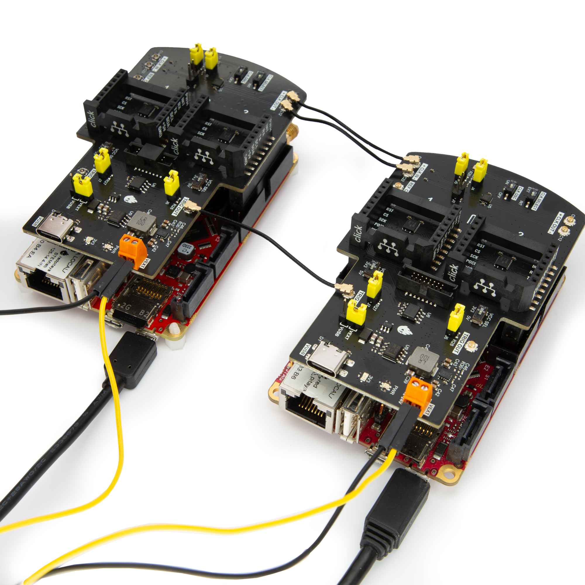
2.3.6.6.2.3. Wiring example
The Red Pitaya Click Shield can synchronise multiple Red Pitaya units together. As U.FL cables are used for clock and trigger synchronisation, other external clock devices can also be included in the chain. The connection provides minimal clock signal delay between multiple Red Pitaya units, as there is only a single ZL40213 LVDS clock fanout buffer between two units.
To synchronise two or more Red Pitaya units, establish the following connections with U.FL cables between the primary board (transmitting clock and trigger signals) and the secondary board (receiving the clock and trigger signals). Use one of the two schemes depending on whether you want to connect an external clock or use the oscillator on the Red Pitaya Click Shields.
2.3.6.6.2.3.1. Oscillator
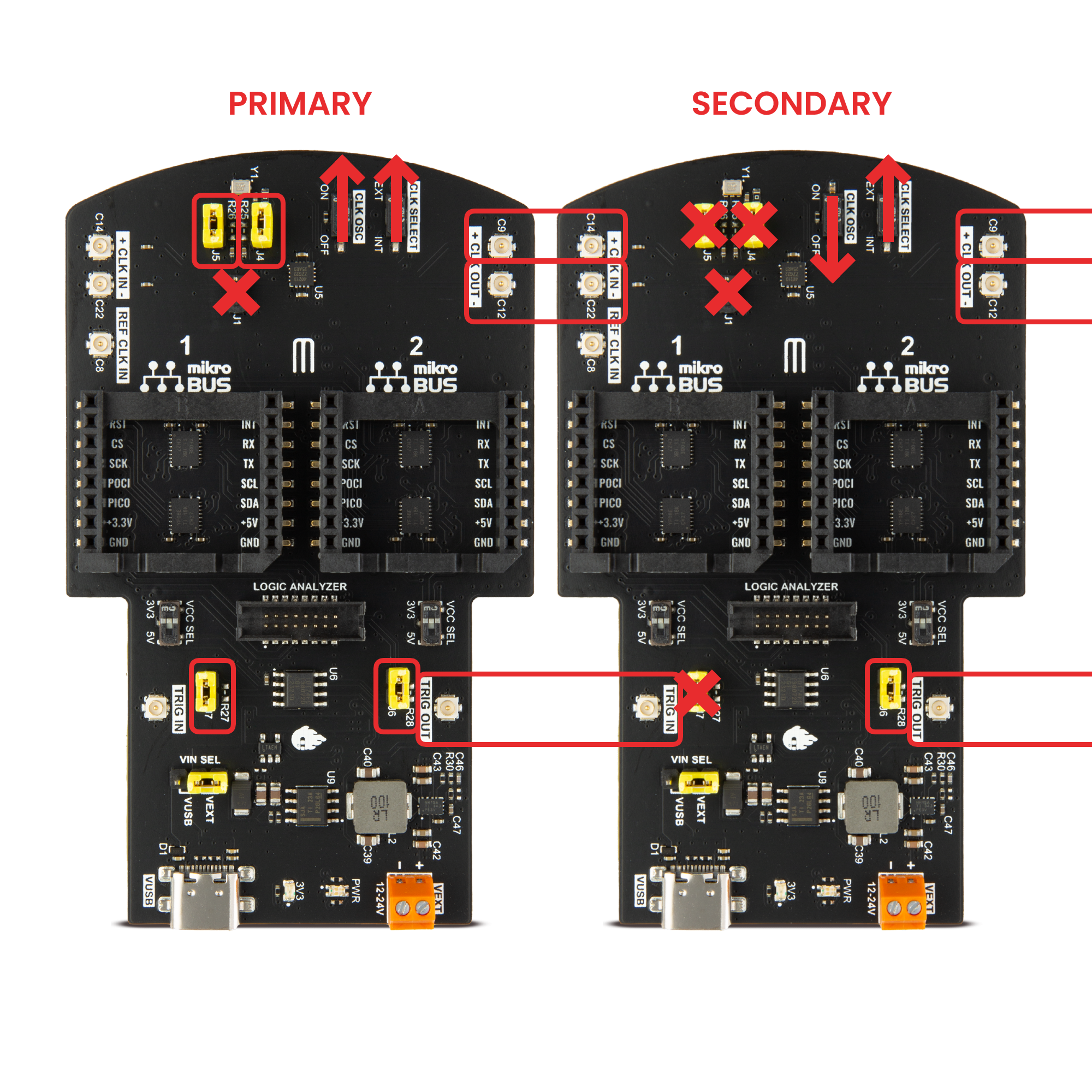
When using the oscillator, the first Red Pitaya Click Shield transmits the clock and trigger signals to all devices in the chain. Here are the most important things to check:
Primary board:
Jumpers J4 and J5 connected. Connect the oscillator to the clocking transmission line.
Jumpers J6 and J7 connected. Connect the Red Pitaya trigger to the trigger transmission line.
Jumper J1 disconnected (unless using a single wire clock).
CLK OSC switch in ON position.
CLK SELECT switch in EXT position.
Secondary board:
Jumper J6 connected. Connect the trigger to the Ext. Trigger pin.
Jumper J1 disconnected (unless using a single wire clock).
CLK OSC switch in OFF position.
CLK SELECT switch in EXT position.
If an external trigger signal is used, copy the secondary board’s trigger connections to the primary board (disconnect J7 and connect the external trigger U.FL cable). Otherwise, DIO0_N acts as external trigger output (on the primary board), and DIO0_P acts as external trigger input.
2.3.6.6.2.3.2. External Clock
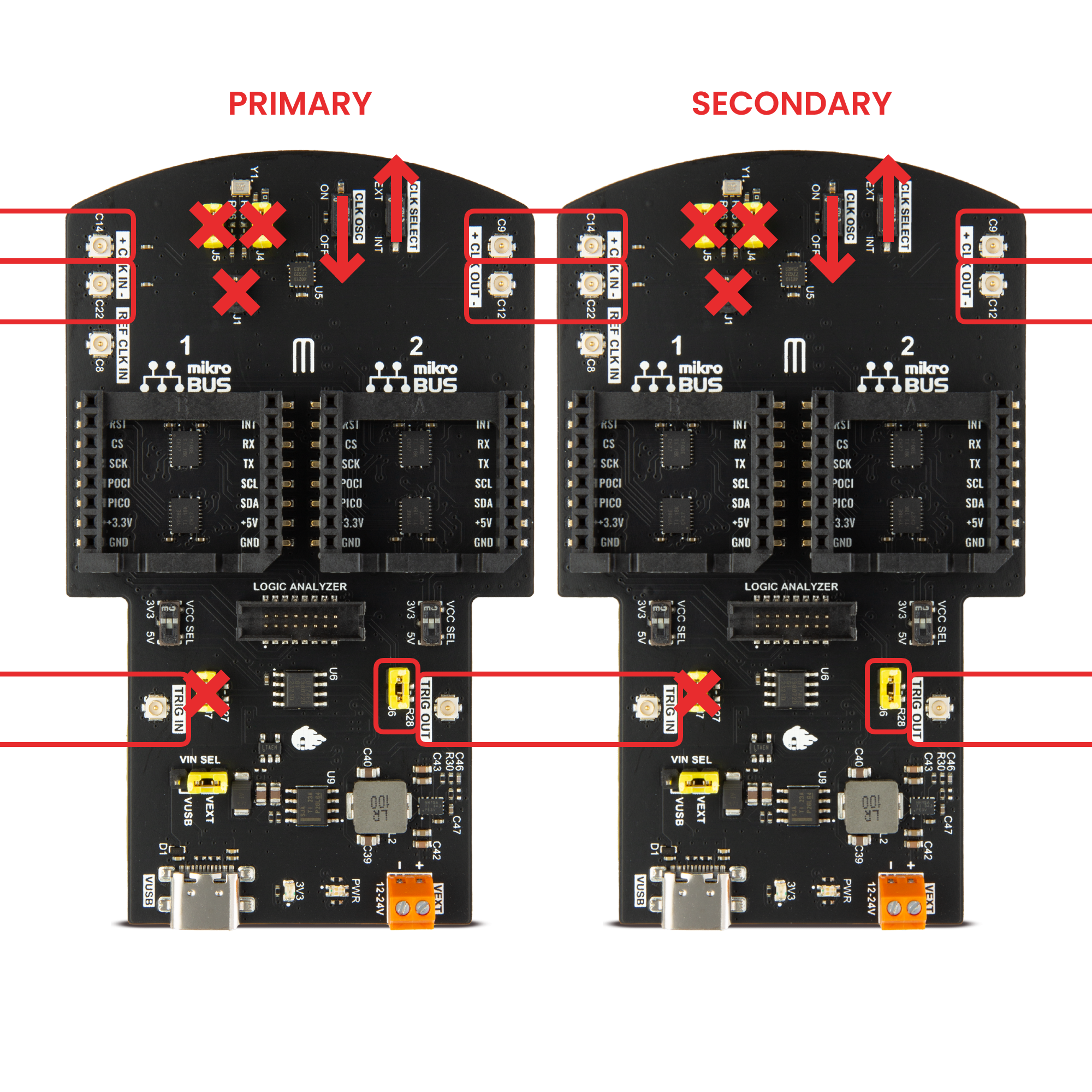
When using an external clock and external trigger, the clock and trigger signals are transmitted to all devices in the chain. All the Click Shields share the same configuration:
Primary and Secondary boards:
Jumper J6 connected. Connect the trigger to the Ext. Trigger pin.
Jumper J1 disconnected (unless using a single wire clock).
CLK OSC switch in OFF position.
CLK SELECT switch in EXT position.
Note
For more information on connectors, switches, and jumper positions, check out the Red Pitaya Click Shield documentation.
Note
The trigger signals from the SATA connector and the DIO0_P (External trigger pin) are OR-ed together in the software. The generation and acquisition trigger fronts apply after the “OR gate” and trigger either DAC or ADC, depending on the DAISY:TRIG_O:SOUR <mode> command.
2.3.6.6.2.4. SCPI Code Examples
Note
This code is written for 2.00-30 or higher OS. For older OS versions, please check when specific commands were released (a note is added to each command introduced in 2.00 or higher verisons).
2.3.6.6.2.4.1. Code - Python
Using just SCPI commands:
#!/usr/bin/env python3
""" Click shield daisy chain example for Red Pitaya. """

import time
import matplotlib.pyplot as plt
import numpy as np

import redpitaya_scpi as scpi

# Connect OUT1 primary with IN1 primary and IN1 secondary

wave_form = "sine"
freq = 100000
ampl = 1

dec = 2
trig_lvl = 0.5
trig_dly = 7000


IP_PRIM = 'rp-f0a235.local'   # IP Test OS Red Pitaya
IP_SEC = 'rp-f0ac90.local'

rp_prim = scpi.scpi(IP_PRIM)
rp_sec = scpi.scpi(IP_SEC)

print("Program Start")

rp_prim.tx_txt('GEN:RST')
rp_prim.tx_txt('ACQ:RST')

rp_sec.tx_txt('GEN:RST')
rp_sec.tx_txt('ACQ:RST')

###### ENABLING THE DAISY CHAIN PRIMARY UNIT ######

rp_prim.tx_txt('DAISY:SYNC:TRig ON')    #! OFF (without sync)
rp_prim.tx_txt('DAISY:SYNC:CLK ON')
rp_prim.tx_txt('DAISY:TRIG_O:ENable ON')     # Enables GPIO0_N as trigger output
rp_prim.tx_txt('DAISY:TRIG_O:SOUR ADC')      # Ext trigger will trigger the ADC

rp_prim.tx_txt('DIG:PIN LED5,1')             # LED Indicator

time.sleep(0.2)

print(f"Trig sync: {rp_prim.txrx_txt('DAISY:SYNC:TRig?')}")
print(f"CLK sync: {rp_prim.txrx_txt('DAISY:SYNC:CLK?')}")
print(f"GPIO0_N trig: {rp_prim.txrx_txt('DAISY:TRIG_O:SOUR?')}\n")
print(f"Source: {rp_prim.txrx_txt('DAISY:TRIG_O:SOUR?')}\n")

###### ENABLING THE DAISY CHAIN SECONDARY UNIT ######

rp_sec.tx_txt('DAISY:SYNC:TRig ON')    #! OFF (without sync)
rp_sec.tx_txt('DAISY:SYNC:CLK ON')
rp_sec.tx_txt('DAISY:TRIG_O:ENable ON')     # Enables GPIO0_N as trigger output
rp_sec.tx_txt('DAISY:TRIG_O:SOUR ADC')      # Ext trigger will trigger the ADC

rp_sec.tx_txt('DIG:PIN LED5,1')             # LED Indicator

print("Start generator\n")


### Generation ### - Primary unit
rp_prim.tx_txt(f'SOUR1:FUNC {wave_form}')
rp_prim.tx_txt(f'SOUR1:FREQ:FIX {freq}')
rp_prim.tx_txt(f'SOUR1:VOLT {ampl}')

rp_prim.tx_txt('OUTPUT1:STATE ON')

### Aquisition ###

# Primary unit
rp_prim.tx_txt(f'ACQ:DEC {dec}')
rp_prim.tx_txt(f'ACQ:TRig:LEV {trig_lvl}')
rp_prim.tx_txt(f'ACQ:TRig:DLY {trig_dly}')

# Secondary unit
rp_sec.tx_txt(f'ACQ:DEC {dec}')
rp_sec.tx_txt(f'ACQ:TRig:LEV {trig_lvl}')
rp_sec.tx_txt(f'ACQ:TRig:DLY {trig_dly}')


rp_sec.tx_txt('ACQ:START')
time.sleep(0.2)                           # Not necessary
rp_sec.tx_txt('ACQ:TRig EXT_NE')          #! CH1_PE (without sync trig) EXT_NE (with sync trig)
                                          # If not synchronised make sure no signal arrives before both units are set up

rp_prim.tx_txt('ACQ:START')
time.sleep(0.2)
rp_prim.tx_txt('ACQ:TRig CH1_PE')

time.sleep(1)                             # Symulating a trigger after one second
rp_prim.tx_txt('SOUR1:TRig:INT')

print("ACQ start")

while 1:
    # Get Trigger Status
    if rp_prim.txrx_txt('ACQ:TRig:STAT?') == 'TD':               # Triggerd?
        break
print("Trigger primary condition met.")

while 1:
    if rp_prim.txrx_txt('ACQ:TRig:FILL?') == '1':
        break
print("Buffer primary filled.")

while 1:
    # Get Trigger Status
    if rp_sec.txrx_txt('ACQ:TRig:STAT?') == 'TD':               # Triggerd?
        break
print("Trigger secondary condition met.")

while 1:
    if rp_sec.txrx_txt('ACQ:TRig:FILL?') == '1':
        break
print("Buffer secondary filled.")


# Read data and plot
rp_prim.tx_txt('ACQ:SOUR1:DATA?')               # Read full buffer primary (source 1)
data_string1 = rp_prim.rx_txt()                 # data into a string

rp_sec.tx_txt('ACQ:SOUR1:DATA?')                # Read full buffer secondary (source 1)
data_string2 = rp_sec.rx_txt()

# Display both buffers at once
n = 2
buff = np.zeros((n,16384))

# Remove brackets and empty spaces + string => float
data_string1 = data_string1.strip('{}\n\r').replace("  ", "").split(',')
data_string2 = data_string2.strip('{}\n\r').replace("  ", "").split(',')
# Transform data into data series
buff[0, :] = list(map(float, data_string1))
buff[1, :] = list(map(float, data_string2))


######## PLOTTING THE DATA #########
fig, axs = plt.subplots(n, sharex = True)               # plot the data (n subplots)
fig.suptitle("Measurements P1 S2")

for i in range(0,n,1):                                  # plotting the acquired buffers
    axs[i].plot(buff[i])

plt.show()

rp_prim.close()
rp_sec.close()
Using functions:
#!/usr/bin/env python3
""" Click shield daisy chain example for Red Pitaya """

import time
import matplotlib.pyplot as plt
import numpy as np

import redpitaya_scpi as scpi

# Connect OUT1 primary with IN1 primary and IN1 secondary


IP_PRIM = 'rp-f0a235.local'   # IP Test OS Red Pitaya
IP_SEC = 'rp-f0ac90.local'

rp_prim = scpi.scpi(IP_PRIM)
rp_sec = scpi.scpi(IP_SEC)

print("Program Start")

rp_prim.tx_txt('GEN:RST')
rp_prim.tx_txt('ACQ:RST')

rp_sec.tx_txt('GEN:RST')
rp_sec.tx_txt('ACQ:RST')

###### ENABLING THE DAISY CHAIN PRIMARY UNIT ######

rp_prim.tx_txt('DAISY:SYNC:TRig ON')    #! OFF (without sync)
rp_prim.tx_txt('DAISY:SYNC:CLK ON')
rp_prim.tx_txt('DAISY:TRIG_O:ENable ON')     # Enables GPIO0_N as trigger output
rp_prim.tx_txt('DAISY:TRIG_O:SOUR ADC')

rp_prim.tx_txt('DIG:PIN LED5,1')            # LED Indicator

time.sleep(0.2)

print(f"Trig sync: {rp_prim.txrx_txt('DAISY:SYNC:TRig?')}")
print(f"CLK sync: {rp_prim.txrx_txt('DAISY:SYNC:CLK?')}")
print(f"GPIO0_N trig: {rp_prim.txrx_txt('DAISY:TRIG_O:SOUR?')}\n")
print(f"Source: {rp_prim.txrx_txt('DAISY:TRIG_O:SOUR?')}\n")

###### ENABLING THE DAISY CHAIN SECONDARY UNIT ######

rp_sec.tx_txt('DAISY:SYNC:TRig ON')  #! OFF (without sync)
rp_sec.tx_txt('DAISY:SYNC:CLK ON')
rp_sec.tx_txt('DAISY:TRIG_O:ENable ON')    # Enables GPIO0_N as trigger output
rp_sec.tx_txt('DAISY:TRIG_O:SOUR ADC')     # Ext trigger will trigger the ADC

rp_sec.tx_txt('DIG:PIN LED5,1')            # LED Indicator

print("Start generator\n")


### Generation ### - Primary unit
rp_prim.sour_set(1, "sine", 1, 100000)
rp_prim.tx_txt('OUTPUT1:STATE ON')

### Aquisition ###

# Primary unit
rp_prim.acq_set(dec = 2,
                trig_lvl = 0.5,
                trig_delay = 7000)


# Secondary unit
rp_sec.acq_set(dec = 2,
               trig_lvl = 0.5,
               trig_delay = 7000)


rp_sec.tx_txt('ACQ:START')
time.sleep(0.2)                           # Not necessary
rp_sec.tx_txt('ACQ:TRig EXT_NE')          #! CH1_PE (without sync trig) EXT_NE (with sync trig)
                                          # If not synchronised make sure no signal arrives before both units are set up

rp_prim.tx_txt('ACQ:START')
time.sleep(0.2)
rp_prim.tx_txt('ACQ:TRig CH1_PE')

time.sleep(1)                             # Symulating a trigger after one second
rp_prim.tx_txt('SOUR1:TRig:INT')

print("ACQ start")

while 1:
    # Get Trigger Status
    if rp_prim.txrx_txt('ACQ:TRig:STAT?') == 'TD':               # Triggerd?
        break
print("Trigger primary condition met.")

while 1:
    if rp_prim.txrx_txt('ACQ:TRig:FILL?') == '1':
        break
print("Buffer primary filled.")

while 1:
    # Get Trigger Status
    if rp_sec.txrx_txt('ACQ:TRig:STAT?') == 'TD':               # Triggerd?
        break
print("Trigger secondary condition met.")

while 1:
    if rp_sec.txrx_txt('ACQ:TRig:FILL?') == '1':
        break
print("Buffer secondary filled.")


# Read data and plot
rp_prim.tx_txt('ACQ:SOUR1:DATA?')               # Read full buffer primary (source 1)
data_string1 = rp_prim.rx_txt()                 # data into a string

rp_sec.tx_txt('ACQ:SOUR1:DATA?')                # Read full buffer secondary (source 1)
data_string2 = rp_sec.rx_txt()

# Display both buffers at once
n = 2
buff = np.zeros((n,16384))

# Remove brackets and empty spaces + string => float
data_string1 = data_string1.strip('{}\n\r').replace("  ", "").split(',')
data_string2 = data_string2.strip('{}\n\r').replace("  ", "").split(',')
# Transform data into data series
buff[0, :] = list(map(float, data_string1))
buff[1, :] = list(map(float, data_string2))


######## PLOTTING THE DATA #########
fig, axs = plt.subplots(n, sharex = True)               # plot the data (n subplots)
fig.suptitle("Measurements P1 S2")

for i in range(0,n,1):                                  # plotting the acquired buffers
    axs[i].plot(buff[i])

plt.show()

rp_prim.close()
rp_sec.close()
Note
The Python functions are accessible with the latest version of the redpitaya_scpi.py document available on our GitHub. The functions represent a quality-of-life improvement as they combine the SCPI commands in an optimal order and also check for improper user inputs. The code should function at approximately the same speed without them.
For further information on functions please consult the redpitaya_scpi.py code.
2.3.6.6.2.5. API Code Examples
Note
The API code examples don’t require the use of the SCPI server. Instead, the code should be compiled and executed on the Red Pitaya itself (inside Linux OS). Instructions on how to compile the code and other useful information are here.
2.3.6.6.2.5.1. Code - Python API
#!/usr/bin/python3

import time
import numpy as np
import rp

########! Primary unit code !#########
channel = rp.RP_CH_1        # rp.RP_CH_2
waveform = rp.RP_WAVEFORM_SINE
freq = 100000
ampl = 1.0

trig_lvl = 0.5
trig_dly = 0

dec = rp.RP_DEC_1

gen_trig_sour = rp.RP_GEN_TRIG_SRC_INTERNAL

acq_trig_sour = rp.RP_TRIG_SRC_CHA_PE

N = 16384

# Initialize the interface
rp.rp_Init()

# Reset Generation and Acquisition
rp.rp_GenReset()
rp.rp_AcqReset()

###### Enable Daisy Chain #####
rp.rp_SetEnableDiasyChainClockSync(True)        # Sync Clock
rp.rp_SetEnableDaisyChainTrigSync(True)         # Sync Trigger
rp.rp_SetDpinEnableTrigOutput(True)             # Enable trigger output on DIO0_N

# Choose which trigger to synchronise (rp.OUT_TR_ADC, rp.OUT_TR_DAC)
rp.rp_SetSourceTrigOutput(rp.OUT_TR_ADC)

# LED indicator
rp.rp_DpinSetState(rp.RP_LED5, rp.RP_HIGH)

###### Generation #####
print("Gen_start")
rp.rp_GenWaveform(channel, waveform)
rp.rp_GenFreqDirect(channel, freq)
rp.rp_GenAmp(channel, ampl)

rp.rp_GenTriggerSource(channel, gen_trig_sour)
rp.rp_GenOutEnable(channel)

##### Acquisition #####
rp.rp_AcqSetDecimation(dec)

# Set trigger level and delay
rp.rp_AcqSetTriggerLevel(rp.RP_T_CH_1, trig_lvl)
rp.rp_AcqSetTriggerDelay(trig_dly)

# Start Acquisition
print("Acq_start")
rp.rp_AcqStart()

# Specify trigger - input 1 positive edge
rp.rp_AcqSetTriggerSrc(acq_trig_sour)

rp.rp_GenTriggerOnly(channel)       # Trigger generator

# Trigger state
while 1:
    trig_state = rp.rp_AcqGetTriggerState()[1]
    if trig_state == rp.RP_TRIG_STATE_TRIGGERED:
        break

# Fill state
print(f"Fill state: {rp.rp_AcqGetBufferFillState()}")

while 1:
    if rp.rp_AcqGetBufferFillState()[1]:
        break

### Get data ###
# Volts
fbuff = rp.fBuffer(N)
res = rp.rp_AcqGetDataV(rp.RP_CH_1, 0, N, fbuff)

data_V = np.zeros(N, dtype = float)

for i in range(0, N, 1):
    data_V[i] = fbuff[i]

print(f"Data in Volts: {data_V}")

# Release resources
rp.rp_Release()


########! Secondary unit code !#########
channel = rp.RP_CH_1        # rp.RP_CH_2
waveform = rp.RP_WAVEFORM_SINE
freq = 100000
ampl = 1.0

trig_lvl = 0.5
trig_dly = 0

dec = rp.RP_DEC_1

# Initialize the interface
rp.rp_Init()

# Reset Generation and Acquisition
rp.rp_GenReset()
rp.rp_AcqReset()

###### Enable Daisy Chain #####
rp.rp_SetEnableDiasyChainClockSync(True)        # Sync Clock
rp.rp_SetEnableDaisyChainTrigSync(True)         # Sync Trigger
rp.rp_SetDpinEnableTrigOutput(True)             # Enable trigger output on DIO0_N

# Choose which trigger to synchronise (rp.OUT_TR_ADC, rp.OUT_TR_DAC)
rp.rp_SetSourceTrigOutput(rp.OUT_TR_ADC)

# LED indicator
rp.rp_DpinSetState(rp.RP_LED5, rp.RP_HIGH)

##### Acquisition #####
rp.rp_AcqSetDecimation(dec)
rp.rp_AcqSetTriggerDelay(trig_dly)

# Start Acquisition
print("Acq_start")
rp.rp_AcqStart()

# Specify trigger - must be EXT_NE
rp.rp_AcqSetTriggerSrc(rp.RP_TRIG_SRC_EXT_NE)

# Trigger state
while 1:
    trig_state = rp.rp_AcqGetTriggerState()[1]
    if trig_state == rp.RP_TRIG_STATE_TRIGGERED:
        break

# Fill state
print(f"Fill state: {rp.rp_AcqGetBufferFillState()}")

while 1:
    if rp.rp_AcqGetBufferFillState()[1]:
        break

### Get data ###

# Volts
fbuff = rp.fBuffer(N)
res = rp.rp_AcqGetDataV(rp.RP_CH_1, 0, N, fbuff)

data_V = np.zeros(N, dtype = float)

for i in range(0, N, 1):
    data_V[i] = fbuff[i]

print(f"Data in Volts: {data_V}")

# Release resources
rp.rp_Release()