2.3.6.5.1. Synchronised one-pulse signal generation and acquisition
2.3.6.5.1.1. Description
This example shows how to acquire 16k samples of signal on fast analog inputs. The signal will be acquired simultaneously with the generated signal. The time length of the acquired signal depends on the time scale of a buffer that can be set with a decimation factor. The decimations and time scales of a buffer are given in the sample rate and decimation. Voltage and frequency ranges depend on the Red Pitaya model.
2.3.6.5.1.2. Required hardware
Red Pitaya device
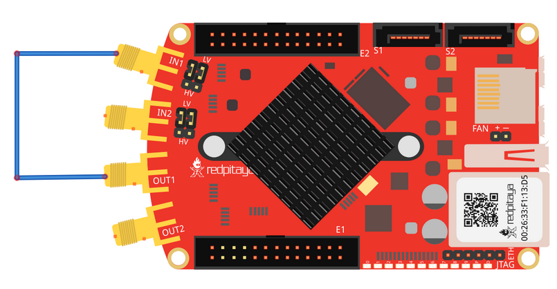
Wiring example for STEMlab 125-14 & STEMlab 125-10:
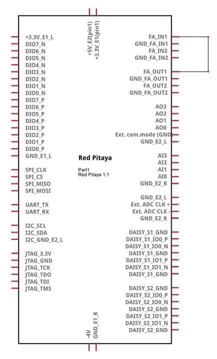
2.3.6.5.1.3. Circuit
2.3.6.5.1.4. SCPI Code Examples
Note
This code is written for 2.00-23 or higher OS. For older OS versions, please check when specific commands were released (a note is added to each command introduced in 2.00 or higher verisons).
Note
With the latest OS versions you can use ACQ:DEC:F <decimation_factor> command for more precise control over the acquisition. The decimation factor can be any of [1, 2, 4, 8, 16, 17, 18, 19, ..., 65535, 65536].
2.3.6.5.1.4.1. Code - MATLAB®
The code is written in MATLAB. In the code, we use SCPI commands and TCP client communication. Copy the code from below into the MATLAB editor, save the project, and hit the “Run” button.
clc
clear all
close all

IP = '192.168.178.111';           % Input IP of your Red Pitaya...
port = 5000;
RP = tcpclient(IP, port);

%% Open connection with your Red Pitaya
RP.ByteOrder = "big-endian";
configureTerminator(RP,"CR/LF");

flush(RP);

% Reset Generation and Acquisition
writeline(RP,'GEN:RST');                        % Reset Generator & Acquisition
writeline(RP,'ACQ:RST');

%% GENERATION
writeline(RP,'SOUR1:FUNC SINE');
writeline(RP,'SOUR1:FREQ:FIX 1000000');         % Set frequency of output signal
writeline(RP,'SOUR1:VOLT 1');                   % Set amplitude of output signal

writeline(RP,'SOUR1:BURS:STAT BURST');      % Set burst mode to BURST
writeline(RP,'SOUR1:BURS:NCYC 3');          % Set 3 pulses of sine wave

%% ACQUISITION
writeline(RP,'ACQ:DEC 1');
writeline(RP,'ACQ:TRig:LEV 0');
writeline(RP,'ACQ:TRig:DLY 0');


%% Start gen % acq

writeline(RP,'ACQ:START');
pause(1);
writeline(RP,'ACQ:TRig AWG_PE');
writeline(RP,'OUTPUT1:STATE ON');           % Set output to ON
pause(1);

writeline(RP,'SOUR1:TRig:INT');

%% Wait for trigger
while 1
    trig_rsp = writeread(RP,'ACQ:TRig:STAT?')
    if strcmp('TD',trig_rsp(1:2))
        break;
    end
end

%%! OS 2.00 or higher only !%%
% wait for fill adc buffer
while 1
    fill_state = writeread(RP,'ACQ:TRig:FILL?')
    if strcmp('1', fill_state(1:1))
        break;
    end
end

%% Read & plot

signal_str = writeread(RP,'ACQ:SOUR1:DATA?');
signal_num = str2num(signal_str(1, 2:length(signal_str) - 3));
plot(signal_num)
grid on

%% Close connection with Red Pitaya
clear RP;
2.3.6.5.1.4.2. Code - Python
Using just SCPI commands:
#!/usr/bin/env python3

import sys
import time
import matplotlib.pyplot as plt
import redpitaya_scpi as scpi

IP = '192.168.178.111'        # 'rp-f066c8.local'
rp_s = scpi.scpi(IP)

wave_form = 'sine'
freq = 1000000
ampl = 1

# Reset Generation and Acquisition
rp_s.tx_txt('GEN:RST')
rp_s.tx_txt('ACQ:RST')

##### Generation #####
rp_s.tx_txt('SOUR1:FUNC ' + str(wave_form).upper())
rp_s.tx_txt('SOUR1:FREQ:FIX ' + str(freq))
rp_s.tx_txt('SOUR1:VOLT ' + str(ampl))

rp_s.tx_txt('SOUR1:BURS:STAT BURST')        # Mode set to BURST
rp_s.tx_txt('SOUR1:BURS:NCYC 3')            # 3 periods in each burst

##### Acqusition #####
rp_s.tx_txt('ACQ:DEC 1')
rp_s.tx_txt('ACQ:TRig:LEV 0')
rp_s.tx_txt('ACQ:TRig:DLY 0')

rp_s.tx_txt('ACQ:START')
time.sleep(1)
rp_s.tx_txt('ACQ:TRig AWG_PE')
rp_s.tx_txt('OUTPUT1:STATE ON')
time.sleep(1)

rp_s.tx_txt('SOUR1:TRig:INT')

# Wait for trigger
while 1:
    rp_s.tx_txt('ACQ:TRig:STAT?')           # Get Trigger Status
    if rp_s.rx_txt() == 'TD':               # Triggerd?
        break

## ! OS 2.00 or higher only ! ##
while 1:
    rp_s.tx_txt('ACQ:TRig:FILL?')
    if rp_s.rx_txt() == '1':
        break

# Read data and plot
rp_s.tx_txt('ACQ:SOUR1:DATA?')              # Read full buffer (source 1)
data_string = rp_s.rx_txt()                 # data into a string

# Remove brackets and empty spaces + string => float
data_string = data_string.strip('{}\n\r').replace("  ", "").split(',')
data = list(map(float, data_string))        # transform data into float

plt.plot(data)
plt.show()
Using functions:
#!/usr/bin/env python3

import sys
import time
import matplotlib.pyplot as plt
import redpitaya_scpi as scpi

IP = '192.168.178.111'        # 'rp-f066c8.local'
rp_s = scpi.scpi(IP)

wave_form = 'sine'
freq = 1000000
ampl = 1

# Reset Generation and Acquisition
rp_s.tx_txt('GEN:RST')
rp_s.tx_txt('ACQ:RST')

##### Generation #####
# Function for configuring Source
rp_s.sour_set(1, wave_form, ampl, freq, burst=True, ncyc=3)

##### Acqusition #####
# Function for configuring Acquisition
rp_s.acq_set(dec=1, trig_lvl=0, trig_delay=0)

rp_s.tx_txt('ACQ:START')
time.sleep(1)
rp_s.tx_txt('ACQ:TRig AWG_PE')
rp_s.tx_txt('OUTPUT1:STATE ON')
time.sleep(1)

rp_s.tx_txt('SOUR1:TRig:INT')

# Wait for trigger
while 1:
    rp_s.tx_txt('ACQ:TRig:STAT?')           # Get Trigger Status
    if rp_s.rx_txt() == 'TD':               # Triggerd?
        break

## ! OS 2.00 or higher only ! ##
while 1:
    rp_s.tx_txt('ACQ:TRig:FILL?')
    if rp_s.rx_txt() == '1':
        break

# Read data and plot
# function for Data Acquisition
data = rp_s.acq_data(1, convert= True)

plt.plot(data)
plt.show()
Note
The Python functions are accessible with the latest version of the redpitaya_scpi.py document available on our GitHub. The functions represent a quality-of-life improvement as they combine the SCPI commands in an optimal order and also check for improper user inputs. The code should function at approximately the same speed without them.
For further information on functions please consult the redpitaya_scpi.py code.
2.3.6.5.1.5. API Code Examples
Note
The API code examples don’t require the use of the SCPI server. Instead, the code should be compiled and executed on the Red Pitaya itself (inside Linux OS). Instructions on how to compile the code and other useful information are here.
2.3.6.5.1.5.1. Code - C API
/* Red Pitaya C API example of Synced Generation and acquisition
on a specific channel */

#include <stdio.h>
#include <stdlib.h>
#include <unistd.h>
#include "rp.h"


int main(int argc, char **argv){

    /* Print error, if rp_Init() function failed */
    if(rp_Init() != RP_OK){
        fprintf(stderr, "Rp api init failed!\n");
    }

    /* Reset Generation and Acquisition */
    rp_GenReset();
    rp_AcqReset();

    /* Generation */
    rp_GenFreq(RP_CH_1, 1000000.0);
    rp_GenAmp(RP_CH_1, 1.0);
    rp_GenWaveform(RP_CH_1, RP_WAVEFORM_SINE);

    rp_GenMode(RP_CH_1, RP_GEN_MODE_BURST);
    rp_GenBurstCount(RP_CH_1, 3);          // Ncyc
    rp_GenBurstRepetitions(RP_CH_1, 1);    // Nor
    rp_GenBurstPeriod(RP_CH_1, 10);        // Period

    rp_GenOutEnable(RP_CH_1);

    /* Acquisition */
    uint32_t buff_size = 16384;
    float *buff = (float *)malloc(buff_size * sizeof(float));

    rp_AcqReset();
    rp_AcqSetDecimation(RP_DEC_1);
    rp_AcqSetTriggerLevel(RP_CH_1, 0.5);    // Trig level is set in Volts while in SCPI
    rp_AcqSetTriggerDelay(0);

    // There is an option to select coupling when using SIGNALlab 250-12
    // rp_AcqSetAC_DC(RP_CH_1, RP_AC);      // enables AC coupling on Channel 1

    // By default LV level gain is selected
    rp_AcqSetGain(RP_CH_1, RP_LOW);         // user can switch gain using this command

    rp_AcqStart();

    /* After the acquisition is started some time delay is needed to acquire fresh samples into buffer
    Here we have used a time delay of one second but you can calculate the exact value taking into account buffer
    length and sampling rate*/

    sleep(1);
    rp_AcqSetTriggerSrc(RP_TRIG_SRC_AWG_PE);
    rp_acq_trig_state_t state = RP_TRIG_STATE_TRIGGERED;

    sleep(0.5);
    rp_GenTrigger(RP_CH_1);         // Trigger generator

    while(1){
        rp_AcqGetTriggerState(&state);
        if(state == RP_TRIG_STATE_TRIGGERED){
            break;
        }
    }

    // !! OS 2.00 or higher only !! //
    bool fillState = false;
    while(!fillState){
        rp_AcqGetBufferFillState(&fillState);
    }

    rp_AcqGetOldestDataV(RP_CH_1, &buff_size, buff);
    int i;
    for(i = 0; i < buff_size; i++){
        printf("%f\n", buff[i]);
    }

    /* Releasing resources */
    free(buff);
    rp_Release();
    return 0;
}
2.3.6.5.1.5.2. Code - Python API
#!/usr/bin/python3

import time
import numpy as np
import rp


#? Possible waveforms:
#?   RP_WAVEFORM_SINE, RP_WAVEFORM_SQUARE, RP_WAVEFORM_TRIANGLE, RP_WAVEFORM_RAMP_UP,
#?   RP_WAVEFORM_RAMP_DOWN, RP_WAVEFORM_DC, RP_WAVEFORM_PWM, RP_WAVEFORM_ARBITRARY,
#?   RP_WAVEFORM_DC_NEG, RP_WAVEFORM_SWEEP

channel = rp.RP_CH_1        # rp.RP_CH_2
waveform = rp.RP_WAVEFORM_SINE
freq = 100000
ampl = 1.0

ncyc = 3
nor = 1
period = 10

trig_lvl = 0.5
trig_dly = 0

#? Possible decimations:
#?  RP_DEC_1, RP_DEC_2, RP_DEC_4, RP_DEC_8, RP_DEC_16, RP_DEC_32, RP_DEC_64,
#?  RP_DEC_128, RP_DEC_256, RP_DEC_512, RP_DEC_1024, RP_DEC_2048, RP_DEC_4096, RP_DEC_8192,
#?  RP_DEC_16384, RP_DEC_32768, RP_DEC_65536

dec = rp.RP_DEC_1

#? Possible generation trigger sources:
#?  RP_GEN_TRIG_SRC_INTERNAL, RP_GEN_TRIG_SRC_EXT_PE, RP_GEN_TRIG_SRC_EXT_NE

gen_trig_sour = rp.RP_GEN_TRIG_SRC_INTERNAL

#? Possible acquisition trigger sources:
#?  RP_TRIG_SRC_DISABLED, RP_TRIG_SRC_NOW, RP_TRIG_SRC_CHA_PE, RP_TRIG_SRC_CHA_NE, RP_TRIG_SRC_CHB_PE,
#?  RP_TRIG_SRC_CHB_NE, RP_TRIG_SRC_EXT_PE, RP_TRIG_SRC_EXT_NE, RP_TRIG_SRC_AWG_PE, RP_TRIG_SRC_AWG_NE,
#?  RP_TRIG_SRC_CHC_PE, RP_TRIG_SRC_CHC_NE, RP_TRIG_SRC_CHD_PE, RP_TRIG_SRC_CHD_NE

acq_trig_sour = rp.RP_TRIG_SRC_AWG_PE

N = 16384


# Initialize the interface
rp.rp_Init()

# Reset Generation and Acquisition
rp.rp_GenReset()
rp.rp_AcqReset()

###### Generation #####
print("Gen_start")
rp.rp_GenWaveform(channel, waveform)
rp.rp_GenFreqDirect(channel, freq)
rp.rp_GenAmp(channel, ampl)

# Change to burst mode
rp.rp_GenMode(channel, rp.RP_GEN_MODE_BURST)
rp.rp_GenBurstCount(channel, ncyc)                  # Ncyc
rp.rp_GenBurstRepetitions(channel, nor)             # Nor
rp.rp_GenBurstPeriod(channel, period)               # Period


# Specify generator trigger source
rp.rp_GenTriggerSource(channel, gen_trig_sour)

# Enable output synchronisation
rp.rp_GenOutEnableSync(True)
rp.rp_GenOutEnable(channel)


##### Acquisition #####
# Set Decimation
rp.rp_AcqSetDecimation(dec)

#? Possible triggers:
#?  RP_T_CH_1, RP_T_CH_2, RP_T_CH_3, RP_T_CH_4, RP_T_CH_EXT

# Set trigger level and delay
rp.rp_AcqSetTriggerLevel(rp.RP_T_CH_1, trig_lvl)
rp.rp_AcqSetTriggerDelay(trig_dly)


# Start Acquisition
print("Acq_start")
rp.rp_AcqStart()

# Specify trigger - input 1 positive edge
rp.rp_AcqSetTriggerSrc(acq_trig_sour)


rp.rp_GenTriggerOnly(channel)       # Trigger generator

print(f"Trigger state: {rp.rp_AcqGetTriggerState()}")

# Trigger state
while 1:
    trig_state = rp.rp_AcqGetTriggerState()[1]
    if trig_state == rp.RP_TRIG_STATE_TRIGGERED:
        break

## ! OS 2.00 or higher only ! ##
# Fill state
print(f"Fill state: {rp.rp_AcqGetBufferFillState()}")

## ! OS 2.00 or higher only ! ##
while 1:
    if rp.rp_AcqGetBufferFillState()[1]:
        break


### Get data ###
# Volts
fbuff = rp.fBuffer(N)
res = rp.rp_AcqGetDataV(rp.RP_CH_1, 0, N, fbuff)

data_V = np.zeros(N, dtype = float)

for i in range(0, N, 1):
    data_V[i] = fbuff[i]

print(f"Data in Volts: {data_V}")

# Release resources
rp.rp_Release()